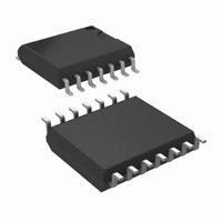
LM2574HVM-12/NOPB National Semiconductor, LM2574HVM-12/NOPB Datasheet - Page 16

LM2574HVM-12/NOPB
Manufacturer Part Number
LM2574HVM-12/NOPB
Description
IC REG SIMPLE SWITCHER 14-SOIC
Manufacturer
National Semiconductor
Series
SIMPLE SWITCHER®r
Type
Step-Down (Buck)r
Datasheet
1.LM2574MX-ADJNOPB.pdf
(24 pages)
Specifications of LM2574HVM-12/NOPB
Internal Switch(s)
Yes
Synchronous Rectifier
No
Number Of Outputs
1
Voltage - Output
12V
Current - Output
500mA
Frequency - Switching
52kHz
Voltage - Input
4 ~ 60 V
Operating Temperature
-40°C ~ 125°C
Mounting Type
Surface Mount
Package / Case
14-SOIC (7.5mm Width)
Power - Output
750mW
Lead Free Status / RoHS Status
Lead free / RoHS Compliant
Other names
*LM2574HVM-12
*LM2574HVM-12/NOPB
LM2574HVM-12
*LM2574HVM-12/NOPB
LM2574HVM-12
www.national.com
LM2574 Series Buck Regulator Design Procedure
Application Hints
INPUT CAPACITOR (C
To maintain stability, the regulator input pin must be by-
passed with at least a 22 µF electrolytic capacitor. The ca-
pacitor’s leads must be kept short, and located near the
regulator.
If the operating temperature range includes temperatures
below −25˚C, the input capacitor value may need to be
larger. With most electrolytic capacitors, the capacitance
value decreases and the ESR increases with lower tempera-
tures and age. Paralleling a ceramic or solid tantalum ca-
pacitor will increase the regulator stability at cold tempera-
tures. For maximum capacitor operating lifetime, the
capacitor’s RMS ripple current rating should be greater than
IN
)
20V
30V
40V
50V
60V
90V
V
R
FIGURE 9. Diode Selection Guide
MBR120P
MBR130P
MBR140P
Schottky
10JQ030
MBR150
MBR160
11DQ03
11DQ04
11DQ05
11DQ06
11DQ09
1N5817
1N5818
1N5819
11JQ04
11JQ05
11JQ06
SR102
SR103
SR104
SR105
SR106
1 Amp Diodes
16
Fast Recovery
INDUCTOR SELECTION
All switching regulators have two basic modes of operation:
continuous and discontinuous. The difference between the
two types relates to the inductor current, whether it is flowing
continuously, or if it drops to zero for a period of time in the
normal switching cycle. Each mode has distinctively different
operating characteristics, which can affect the regulator per-
formance and requirements.
The LM2574 (or any of the Simple Switcher family) can be
used for both continuous and discontinuous modes of opera-
tion.
In many cases the preferred mode of operation is in the con-
tinuous mode. It offers better load regulation, lower peak
switch, inductor and diode currents, and can have lower out-
put ripple voltage. But it does require relatively large inductor
values to keep the inductor current flowing continuously, es-
pecially at low output load currents.
To simplify the inductor selection process, an inductor selec-
tion guide (nomograph) was designed (see Figure 4 through
Figure 8 ). This guide assumes continuous mode operation,
and selects an inductor that will allow a peak-to-peak induc-
tor ripple current ( I
maximum design load current. In the LM2574 SIMPLE
SWITCHER, the peak-to-peak inductor ripple current per-
centage (of load current) is allowed to change as different
design load currents are selected. By allowing the percent-
age of inductor ripple current to increase for lower current
applications, the inductor size and value can be kept rela-
tively low.
following
MUR110
HER102
rated to
diodes
11DF1
are all
10JF1
100V
The
(Continued)
IND
) to be a certain percentage of the


