LM2576T-012G ON Semiconductor, LM2576T-012G Datasheet - Page 20
LM2576T-012G
Manufacturer Part Number
LM2576T-012G
Description
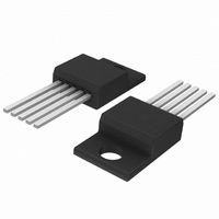
IC REG SW 3A 12V STEPDWN TO220-5
Manufacturer
ON Semiconductor
Type
Step-Down (Buck)r
Datasheet
1.LM2576D2T-ADJR4G.pdf
(28 pages)
Specifications of LM2576T-012G
Internal Switch(s)
Yes
Synchronous Rectifier
No
Number Of Outputs
1
Voltage - Output
12V
Current - Output
3A
Frequency - Switching
52kHz
Voltage - Input
7 ~ 40 V
Operating Temperature
-40°C ~ 125°C
Mounting Type
Through Hole
Package / Case
TO-220-5 (Straight Leads)
Output Voltage
12 V
Output Current
3 A
Input Voltage
4.75 V to 40 V
Switching Frequency
52 KHz
Operating Temperature Range
- 40 C to + 125 C
Mounting Style
Through Hole
Duty Cycle (max)
98 %
Lead Free Status / RoHS Status
Lead free / RoHS Compliant
Power - Output
-
Lead Free Status / Rohs Status
Lead free / RoHS Compliant
Available stocks
Company
Part Number
Manufacturer
Quantity
Price
Company:

Part Number:
LM2576T-012G
Manufacturer:
ON Semiconductor
Quantity:
2 000


Negative Boost Regulator
and it is called negative boost regulator. This regulator
experiences relatively high switch current, especially at low
input voltages. The internal switch current limiting results in
lower output load current capability.
configuration. The input voltage in this application ranges
from −5.0 V to −12 V and provides a regulated −12 V output.
If the input voltage is greater than −12 V, the output will rise
above −12 V accordingly, but will not damage the regulator.
Design Recommendations:
buck−boost converter can be applied. The output capacitor
C
standard buck converter. Low input voltages or high output
currents require a large value output capacitor (in the range
of thousands of mF). The recommended range of inductor
values for the negative boost regulator is the same as for
inverting converter design.
V
−5.0 V to −12 V
Figure 29. Inverting Buck−Boost Regulator Shutdown
100 mF
in
out
This example is a variation of the buck−boost topology
The circuit in Figure 30 shows the negative boost
The same design rules as for the previous inverting
C
must be chosen larger than would be required for a what
NOTE: This picture does not show the complete circuit.
in
+V
in
+V
0
V
Figure 30. Negative Boost Regulator
1
Circuit Using a PNP Transistor
in
On
C
100 mF
in
3
Off
LM2576−12
5.6 k
100 mH
GND
R2
Q1
2N3906
Shutdown
Input
5
+V
1
in
ON/OFF
5
Feedback
Output
4
2
LM2576−XX
ON/OFF
R1
12 k
Typical Load Current
400 mA for V
750 mA for V
1N5820
3
GN
D
−V
V
in
in
out
C
2200 mF
Low Esr
out
= −5.2 V
= −7.0 V
http://onsemi.com
out
= −12 V
LM2576
20
converters cannot provide current limiting load protection in
the event of a short in the output so some other means, such
as a fuse, may be necessary to provide the load protection.
Delayed Startup
already mentioned above, which require a higher amount of
startup current. In such cases, if the input power source is
limited, this delayed startup feature becomes very useful.
voltage is applied and the time when the output voltage
comes up, the circuit in Figure 31 can be used. As the input
voltage is applied, the capacitor C1 charges up, and the
voltage across the resistor R2 falls down. When the voltage
on the ON/OFF pin falls below the threshold value 1.3 V, the
regulator starts up. Resistor R1 is included to limit the
maximum voltage applied to the ON/OFF pin. It reduces the
power supply noise sensitivity, and also limits the capacitor
C1 discharge current, but its use is not mandatory.
respectively) ripple voltage exists, a long delay time can
cause some problems by coupling the ripple into the
ON/OFF pin, the regulator could be switched periodically
on and off with the line (or double) frequency.
Undervoltage Lockout
the input voltage reaches a certain threshold level. Figure 32
shows an undervoltage lockout circuit applied to a buck
regulator. A version of this circuit for buck−boost converter
is shown in Figure 33. Resistor R3 pulls the ON/OFF pin
high and keeps the regulator off until the input voltage
reaches a predetermined threshold level with respect to the
ground Pin 3, which is determined by the following
expression:
Another important point is that these negative boost
There are some applications, like the inverting regulator
To provide a time delay between the time when the input
When a high 50 Hz or 60 Hz (100 Hz or 120 Hz
Some applications require the regulator to remain off until
NOTE: This picture does not show the complete circuit.
100 mF
+V
Figure 31. Delayed Startup Circuitry
in
V
C
in
th
[ V
Z1
) 1.0 ) R2
C1
0.1 mF
47 k
R1
+V
in
1
R1
5
LM2576−XX
ON/OFF
R2
47 k
V
BE
( Q1 )
3
GN
D
Related parts for LM2576T-012G
Image
Part Number
Description
Manufacturer
Datasheet
Request
R

Part Number:
Description:
Manufacturer:
ON Semiconductor
Datasheet:

Part Number:
Description:
IC REG SW 3A 5V STEPDOWN TO220-5
Manufacturer:
ON Semiconductor
Datasheet:

Part Number:
Description:
IC REG SW 3A 5V STEPDOWN TO220-5
Manufacturer:
ON Semiconductor
Datasheet:
Part Number:
Description:
IC REG SW 3A 3.3V STPDWN TO220-5
Manufacturer:
ON Semiconductor
Datasheet:
Part Number:
Description:
IC REG SW 3A ADJ STEPDWN TO220-5
Manufacturer:
ON Semiconductor
Datasheet:
Part Number:
Description:
IC REG SW 3A ADJ STEPDWN TO220-5
Manufacturer:
ON Semiconductor
Datasheet:
Part Number:
Description:
IC REG SW 3A 3.3V STPDWN TO220-5
Manufacturer:
ON Semiconductor
Datasheet:
Part Number:
Description:
IC REG SW 3A 15V STEPDWN TO220-5
Manufacturer:
ON Semiconductor
Datasheet:
Part Number:
Description:
IC REG SW 3A 12V STEPDWN TO220-5
Manufacturer:
ON Semiconductor
Datasheet:
Part Number:
Description:
IC REG SW 3A 15V STEPDWN TO220-5
Manufacturer:
ON Semiconductor
Datasheet:
Part Number:
Description:
Switching Converters, Regulators & Controllers 15V 3A Buck PWM
Manufacturer:
ON Semiconductor
Part Number:
Description:
ON Semiconductor [VOLTAGE REGULATOR]
Manufacturer:
ON Semiconductor
Datasheet:
Part Number:
Description:
357-036-542-201 CARDEDGE 36POS DL .156 BLK LOPRO
Manufacturer:
ON Semiconductor
Datasheet:
Part Number:
Description:
357-036-542-201 CARDEDGE 36POS DL .156 BLK LOPRO
Manufacturer:
ON Semiconductor
Datasheet:
Part Number:
Description:
357-036-542-201 CARDEDGE 36POS DL .156 BLK LOPRO
Manufacturer:
ON Semiconductor
Datasheet: