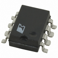
TOP414G Power Integrations, TOP414G Datasheet - Page 13

TOP414G
Manufacturer Part Number
TOP414G
Description
IC SW PWM DC-DC 48VDC 12W 8SMD
Manufacturer
Power Integrations
Series
TOPSwitch®r
Type
Step-Down (Buck), Step-Up (Boost), Flyback, Forward Converterr
Datasheet
1.TOP414GN-TL.pdf
(16 pages)
Specifications of TOP414G
Internal Switch(s)
Yes
Synchronous Rectifier
No
Number Of Outputs
1
Frequency - Switching
120kHz
Operating Temperature
-40°C ~ 125°C
Mounting Type
Surface Mount
Package / Case
8-SMD Gull Wing
Output Voltage
5.8 V
Input / Supply Voltage (max)
265 VAC
Input / Supply Voltage (min)
85 VAC
Duty Cycle (max)
70 %
Switching Frequency
120 KHz
Supply Current
1.4 mA
Operating Temperature Range
- 40 C to + 150 C
Mounting Style
SMD/SMT
Lead Free Status / RoHS Status
Contains lead / RoHS non-compliant
Current - Output
-
Voltage - Output
-
Voltage - Input
-
Power - Output
-
Lead Free Status / Rohs Status
Lead free / RoHS Compliant
Available stocks
Company
Part Number
Manufacturer
Quantity
Price
Part Number:
TOP414G
Manufacturer:
POWER
Quantity:
20 000
Company:
Part Number:
TOP414GN
Manufacturer:
INFINEON
Quantity:
164
Company:
Part Number:
TOP414GN
Manufacturer:
PowerInt
Quantity:
50
Part Number:
TOP414GN
Manufacturer:
POWER
Quantity:
20 000
Company:
Part Number:
TOP414GN-TL
Manufacturer:
POWER
Quantity:
12 000
Part Number:
TOP414GN-TL
Manufacturer:
POWER
Quantity:
20 000
Typical Performance Characteristics
The following precautions should be followed when testing
TOPSwitch by itself outside of a power supply. The schematic
shown in Figure 11 is suggested for laboratory testing of
TOPSwitch.
When the DRAIN supply is turned on, the part will be in the
auto-restart mode. The CONTROL pin voltage will be oscillating
at a low frequency from 4.7 to 5.7 V and the DRAIN is turned
on every eighth cycle of the CONTROL pin oscillation. If the
BENCH TEST PRECAUTIONS FOR EVALUATION OF ELECTRICAL CHARACTERISTICS
CURRENT LIMIT vs. TEMPERATURE
BREAKDOWN vs. TEMPERATURE
1.2
1.0
0.8
0.6
0.4
0.2
1.1
1.0
0.9
0
-50 -25
-50 -25
Junction Temperature (°C)
Junction Temperature (°C)
0
0
25
25
50
50
75 100 125 150
75 100 125 150
CONTROL pin power supply is turned on while in this auto-
restart mode, there is only a 12.5% chance that the CONTROL
pin oscillation will be in the correct state (DRAIN active state)
so that the continuous DRAIN voltage waveform may be
observed. It is recommended that the V
turned on first and the DRAIN power supply second if continuous
drain voltage waveforms are to be observed. The 12.5% chance
of being in the correct state is due to the 8:1 counter.
FREQUENCY vs. TEMPERATURE
1.2
1.0
0.8
0.6
0.4
0.2
1.6
1.2
0.8
0.4
0
2
0
-50 -25
0
I
C
V C = 5 V
vs. DRAIN VOLTAGE
Junction Temperature (°C)
20
0
Drain Voltage (V)
25
40
50
60
75 100 125 150
TOP412/414
C
80
power supply be
100
4/99
A
13


