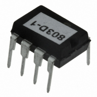
RF803D RF Solutions, RF803D Datasheet

RF803D
Specifications of RF803D
Related parts for RF803D
RF803D Summary of contents
Page 1
... RF800 part can be used with an off the shelf counterpart. Part Number RF803E RF803D ‘ ‘ Operation. Description Encoder IC Decoder IC, 8 pin © © ’ ’ Packages available 6 PIN SOT23 8 PIN PDIP 8 PIN SOIC 8 PIN PDIP . RF803E RF803D 6 5 ...
Page 2
... Each RF803E is programmed at the time of manufacture with a unique 16-bit serial number, which provides a secure way of addressing RF800 series devices. This provides up to 65,536 possible addresses. Compatibility with RF Solutions Receivers The RF803 series are compatible with the FireFly/FireBlade series and 210-433/525/458 series of ready to operate receiver decoder units. ...
Page 3
E E Pin Descriptions RF803E See Page 8 for typical application circuit SOT23 Pin Name Number GND Vcc PDIP Pin Name Number Vcc 3 ...
Page 4
... The RF803D is connected directly to the data output of a radio receiver module and upon detection of a valid data packet it will decode the data stream. The RF803D will then assert its digital outputs which will match the state of the RF803E encoders’ learnt at the time of transmission. ...
Page 5
... E E Pin Descriptions RF803D See Page 8 for application circuit example SOIC / PDIP Pin Name Number 7 OP1 6 OP2 5 OP3 1 Vcc 8 Vss 2 SD/ML 3 LRN 4 Rx Vcc 2.5-5.5V DC input. The power supply needs stable regulated voltage with <10mV ripple GND Ground connection. OP1-3 These outputs are asserted LOW when the relevant inputs (S1 – S3) on the RF803E are asserted. ...
Page 6
... Serial data is output initially and again every ½ second whilst data is being received from the RF803E transmitter. i.e. this output is valid regardless of whether the RF803E encoder has been learnt to the RF803D decoder or not. The serial data packet contains a learn bit to show if an encoder input is learnt. ...
Page 7
... Serial Data is sent every 1/2 second as a stream of 7 bytes at 9.6K baud. The serial data format is: 8 data bits with 1 stop bit, no parity. Serial data is output form the Decoder chip whenever a valid data packet from an RF80n or other compatible RF Solutions transmitter is received regardless of learn N Encoder Serial Number [NN]: made up of two 8-bit bytes where the most significant byte is transmitted first ...
Page 8
... To mark the end of the serial packet ascii characters for carriage return (hex 0D) are sent followed by LF (hex 0A). Custom Versions Custom versions of the RF803E / RF803D chipset are available to provide a bespoke remote chipset for OEM applications. Please contact our sales department for further information. *NOTE: Serial Data output is common across the entire RF80n range, therefore inputs states are sent ...
Page 9
... E E Typical Applications: RF803D RF803E 1 ENABLE GND ‘ ‘ ANTENNA ANT 6 RTFQ1 GND 5 Vcc 4 0.1uF, 25V GND © © ’ ’ s Vcc 0.1uF, 25V RF803E N/C 2 GND 7 VCC N I I/P 2 GND NAND Gate I GND . ...
Page 10
... Standby current High level Input voltage Low level input voltage High level output voltage Low level output voltage Output Pin Current rating LED sink current RF803D Electrical Characteristics Operating current(average) Vdd = 2V Standby current High level Input voltage Low level input voltage ...
Page 11
E E Appendix – Package types 6 PIN SOT-23 PACKAGE ‘ ‘ ...
Page 12
PIN SOIC PACKAGE ‘ ‘ ...
Page 13
PIN PDIP PACKAGE ‘ ‘ ...


