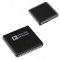
ADMC200AP Analog Devices Inc, ADMC200AP Datasheet - Page 12

ADMC200AP
Manufacturer Part Number
ADMC200AP
Description
IC MOTION CO-PROC 12.5MHZ 68PLCC
Manufacturer
Analog Devices Inc
Datasheet
1.ADMC200AP.pdf
(12 pages)
Specifications of ADMC200AP
Rohs Status
RoHS non-compliant
Applications
*
Mounting Type
Surface Mount
Package / Case
68-PLCC
ADMC200
Bit 8
Bit 10
Bit 3
0
0
1
1
Table VI. SYSCTRL Analog Input Channel Selection
Bit 4
0
1
0
1
IRQ Pin Format—Edge or Level Interrupt Selection.
If Bit 8 is set to 0, then an interrupt will cause a pulse
of one system clock to be generated on the IRQ pin.
If Bit 8 is set to 1, then an interrupt causes the IRQ
output to go LOW (logic 0). The IRQ output pin
will remain LOW until the SYSSTAT register is read.
If Bit 10 is set to 1, then the reverse Park transforma-
tion will be formed in 3/3 mode. For Forward
transformations, this bit must be set to 1.
Channels Converted
V, W (Default)
V, W, AUX
U, V, W
U, V, W, AUX
10
26
27
9
0.954 (24.23)
0.950 (24.13)
0.995 (25.27)
0.985 (25.02)
(PINS DOWN)
TOP VIEW
IDENTIFIER
PIN 1
SQ
SQ
68-Lead Plastic Leaded Chip Carrier (PLCC)
Mode
Two/Three Phase
Two/Three Phase
Three/Three Phase
Three/Three Phase
43
61
Dimensions shown in inches and (mm).
60
44
OUTLINE DIMENSIONS
0.175 (4.45)
0.169 (4.29)
0.104 (2.64) TYP
(P-68A)
–12–
0.050
(1.27)
TYP
0.029 (0.74)
0.027 (0.69)
0.019 (0.48)
0.017 (0.43)
Bit
0
1
4
11
NOTES
1
2
Bit 0
Bit 1
Bit 4
Bit 11
Reading this register clears the interrupt status flags Bits 0, 1 and 11.
Undefined until the first Vector Transformation has started
0.925 (23.50)
0.895 (22.73)
Table VII. System Status Register (SYSSTAT)
A/D Conversion Completion Interrupt. This register
is set to 1 when the A/D conversion process has com-
pleted and ADC interrupts have been enabled in the
SYSCTRL register.
Interrupt Status. This register is set to 1 when the
Vector Transformation is completed and the Vector
Transformation completion interrupts have been
enabled.
This bit is set to 1 when the rotation results are valid.
If any interrupt source on the ADMC200 occurs, then
this bit is set to 1.
Function
A/D Conversion
Completion Interrupt
(1 = True)
Vector Transformation
Completion Interrupt
(1 = True)
Rotation Results are Valid
(1 = Valid)
IRQ Generated from This
Device (1 = True)
BOTTOM VIEW
IDENTIFIER
(PINS UP)
PIN 1
RESET
Default
0
0
X
0
2
1
REV. B


