ADMC201AP Analog Devices Inc, ADMC201AP Datasheet - Page 13

ADMC201AP
Manufacturer Part Number
ADMC201AP
Description
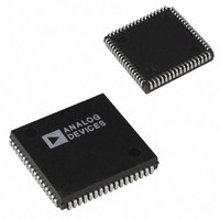
IC MOTION CO-PROC 25MHZ 68PLCC
Manufacturer
Analog Devices Inc
Datasheet
1.ADMC201AP.pdf
(15 pages)
Specifications of ADMC201AP
Rohs Status
RoHS non-compliant
Applications
*
Mounting Type
Surface Mount
Package / Case
68-PLCC
Operating Temperature (min)
-40C
Operating Temperature (max)
85C
Operating Temperature Classification
Industrial
Mounting
Surface Mount
Lead Free Status / RoHS Status
Not Compliant
Available stocks
Company
Part Number
Manufacturer
Quantity
Price
REV. B
Bit
0
1
3
4
5
6
7
8
10
Bit 0
0
0
1
1
Table VI. SYSCTRL Auxiliary Channel Selection
Table V. System Control (SYSCTRL) Registers
Function
Auxiliary Channel Selection
Auxiliary Channel Selection
Enables U Channel Conversion
(1 = Enable) Two-/Three-Phase Mode
Enables AUX Channel Conversion
(0 = Disable, 1 = Enable)
Divide External Clock by 2
(0 = No, 1 = Yes)
Park Interrupt Enable
ADC Interrupt Enable
(0 = Disable, 1 = Enable)
IRQ Pin Format (Edge or Level Based
Interrupt Requests) (0 = Edge)
Reverse Rotation (0 = 2/3, 1 = 3/3)
Forward Rotation (1 = Enable)
Bit 1
0
1
0
1
Auxiliary Channels Converted
AUX0
AUX1
AUX2
AUX3
RESET
Default
0
0
0
0
0
0
0
0
0
–13–
Bit 3
0
0
1
1
Bit 0, 1 Auxiliary Channel Selection.
Bit 3
Bit 4
Bit 5
Bit 6
Bit 7
Bit 8
Bit 10
Table VII. SYSCTRL Analog Input Channel Selection
Bit 4
0
1
0
1
If Bit 8 is set to 0, then an interrupt will cause a
pulse of one system clock to be generated on the
IRQ pin. If Bit 8 is set to 1, then an interrupt
causes the IRQ output to go LOW (logic 0). The IRQ
output pin will remain LOW until the SYSSTAT
register is read.
tion will be formed in 3/3 mode. For Forward
transformations, this bit must be set to 1.
Channel U Conversion Enable. If Bit 3 is set to 1, then
Channel U will be converted along with V, W and/or
AUX. This bit selects three-/three-phase mode.
Aux Channel Conversion Enable. If Bit 4 is set to
1, then the AUX input will be converted along with
the channels V, W and/or U.
If Bit 5 = 1, then the external clock will be divided by
two to derive the system clock. If the external clock
frequency is greater than 12.5 MHz, then this bit must
be set.
Park Interrupt Enable. This bit allows interrupts to
be generated when the Park rotation is completed.
ADC Interrupt Enable. This bit allows interrupts to
be generated when the analog-to-digital conversion
process is complete.
IRQ Pin Format—Edge or Level Interrupt Selection.
If Bit 10 is set to 1, then the reverse Park transforma-
Channels Converted
V, W (Default)
V, W, AUX
U, V, W
U, V, W, AUX
Mode
Two-/Three-Phase
Two-/Three-Phase
Three-/Three-Phase
Three-/Three-Phase
ADMC201


