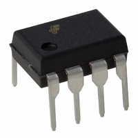
MID400 Fairchild Optoelectronics Group, MID400 Datasheet - Page 4

MID400
Manufacturer Part Number
MID400
Description
OPTOCOUPLER LOGIC-OUT 8-DIP
Manufacturer
Fairchild Optoelectronics Group
Datasheet
1.MID400.pdf
(11 pages)
Specifications of MID400
Voltage - Isolation
2500Vrms
Number Of Channels
1, Unidirectional
Current - Output / Channel
3mA
Input Type
AC
Output Type
Open Collector
Mounting Type
Through Hole
Package / Case
8-DIP
Lead Free Status / RoHS Status
Lead free / RoHS Compliant
Other names
MID400GI
MID400QT
MID400QT
MID400QT
MID400QT
Available stocks
Company
Part Number
Manufacturer
Quantity
Price
Part Number:
MID400
Manufacturer:
FAIRCHILD/仙童
Quantity:
20 000
Company:
Part Number:
MID400S
Manufacturer:
EVERLIGHT
Quantity:
56 000
Company:
Part Number:
MID400SD
Manufacturer:
FSC
Quantity:
4 600
Part Number:
MID400SD
Manufacturer:
FAIRCHILD/仙童
Quantity:
20 000
©2005 Fairchild Semiconductor Corporation
MID400 Rev. 1.0.4
Description/Applications
The input of the MID400 consists of two back-to-back
LED diodes which will accept and convert alternating
currents into light energy. An integrated photo diode-
detector amplifier forms the output network. Optical cou-
pling between input and output provides 2500 VRMS
voltage isolation. A very high current transfer ratio
(defined as the ratio of the DC output current and the DC
input current) is achieved through the use of high gain
amplifier. The detector amplifier circuitry operates from a
5V DC supply and drives an open collector transistor
output. The switching times are intentionally designed to
be slow in order to enable the MID400, when used as an
AC line monitor, to respond only to changes in input volt-
age exceeding many milliseconds. The short period of
time during zero-crossing which occurs once every half
cycle of the power line is completely ignored. To operate
the MID400, always add a resistor, R
input (as shown in test circuit 1) to limit the current to the
required value. The value of the resistor can be deter-
mined by the following equation:
Where,
V
I
“O” on the output.
Pin Description
Schematic Diagram
V
IN
F
Number
IN
is the forward voltage drop across the LED.
(RMS) is the desired input current required to sustain a logic
(RMS) is the input voltage.
Pin
1, 3
2, 4
8
7
6
5
V IN1
V IN2
N/C
N/C
V
Name
IN1
GND
AUX
Pin
V
N/C
V
, V
CC
1
2
3
4
O
R
IN2
IN
=
Input terminals
No Connect
Supply voltage, output circuit.
Auxiliary terminal.
Programmable capacitor input
to adjust AC voltage sensing
level and time delay.
Output terminal; open collector.
Circuit ground potential.
V
---------------------- -
IN
I
IN
–
V
F
Function
IN
8
7
6
5
, in series with the
V CC
AUX.
V O
GND
4
Glossary
VOLTAGES
V
V
V
V
V
CURRENTS
I
I
I
*Current flowing out of a terminal is a negative value.
I (ON)
I (OFF)
OH
I (ON)
I (OFF)
OL
OH
F
RMS
RMS On-State RMS Input Voltage
RMS Off-state RMS Input Current
RMS Off-State RMS Input Voltage
The RMS voltage at an input terminal for a
specified input current with output condi-
tions applied that according to the product
specification will cause the output switch-
ing element to be sustained in the on-state
within one full cycle.
The RMS voltage at an input terminal for a
specified input current with output condi-
tions applied that according to the product
specification will cause the output switch-
ing element to be sustained in the off-state
within one full cycle.
Low-Level Output Voltage
The voltage at an output terminal for a spe-
cific output current I
tions applied that according to the product
specification will establish a low-level at
the output.
High-Level Output Voltage
The voltage at an output terminal for a spe-
cific output current I
tions applied that according to the product
specification will establish a high-level at
the output.
LED Forward Voltage
The voltage developed across the LED
when input current I
anode of the LED.
On-State RMS Input Current
The RMS current flowing into an input with
output conditions applied that according to
the product specification will cause the
output switching element to be sustained
in the on-state within one full cycle.
The RMS current flowing into an input with
output conditions applied that according to
the product specification will cause the
output switching element to be sustained
in the off-state within one full cycle.
High-Level Output Current
The current flowing into * an output with
input conditions applied that according to
the product specification will establish a
high-level at the output.
OH
OL
F
, with input condi-
, with input condi-
is applied to the
www.fairchildsemi.com


