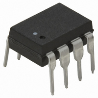
HCPL-3180-000E Avago Technologies US Inc., HCPL-3180-000E Datasheet - Page 13

HCPL-3180-000E
Manufacturer Part Number
HCPL-3180-000E
Description
OPTOCOUPLER 2.0A 250KHZ 8-DIP
Manufacturer
Avago Technologies US Inc.
Datasheet
1.HCPL-3180-000E.pdf
(16 pages)
Specifications of HCPL-3180-000E
Package / Case
8-DIP (0.300", 7.62mm)
Voltage - Isolation
3750Vrms
Number Of Channels
1, Unidirectional
Current - Output / Channel
2.5A
Propagation Delay High - Low @ If
150ns @ 10mA
Current - Dc Forward (if)
16mA
Input Type
DC
Output Type
Gate Driver
Mounting Type
Through Hole
Isolation Voltage
3750 Vrms
Maximum Fall Time
0.025 us
Maximum Forward Diode Current
25 mA
Minimum Forward Diode Voltage
1.2 V
Output Device
Integrated Photo IC
Configuration
1 Channel
Maximum Forward Diode Voltage
1.8 V
Maximum Reverse Diode Voltage
5 V
Maximum Power Dissipation
295 mW
Maximum Operating Temperature
+ 100 C
Minimum Operating Temperature
- 40 C
Number Of Elements
1
Forward Voltage
1.8V
Forward Current
25mA
Package Type
PDIP
Operating Temp Range
-40C to 100C
Power Dissipation
295mW
Propagation Delay Time
200ns
Pin Count
8
Mounting
Through Hole
Reverse Breakdown Voltage
5V
Operating Temperature Classification
Industrial
No. Of Channels
1
Optocoupler Output Type
Gate Drive
Input Current
16mA
Output Voltage
20V
Opto Case Style
DIP
No. Of Pins
8
Common Mode Ratio
10 KV/uS
Rohs Compliant
Yes
Lead Free Status / RoHS Status
Lead free / RoHS Compliant
Lead Free Status / RoHS Status
Lead free / RoHS Compliant, Lead free / RoHS Compliant
Other names
516-1674-5
Available stocks
Company
Part Number
Manufacturer
Quantity
Price
Company:
Part Number:
HCPL-3180-000E
Manufacturer:
AVAGO
Quantity:
6 236
Part Number:
HCPL-3180-000E
Manufacturer:
AVAGO/安华高
Quantity:
20 000
Thermal Model
(Discussion applies to HCPL-3180)
The steady state thermal model for the HCPL-3180 is
shown in Figure 27. The thermal resistance values given
in this model can be used to calculate the temperatures
at each node for a given operating condition. As shown
by the model, all heat generated flows through q
raises the case temperature TC accordingly. The value of
q
is, therefore, determined by the designer. The value of
For example, given P
P
T
placement (q
13
JE
CA
O
= 250 mW, T
and T
depends on the conditions of the board design and
θ
T
Figure 27. Thermal model.
JD
T
T
T
T
T
LC
JE
JD
JE
JD
JE
JD
should be limited to +125 °C based on the board layout and part
= 467 °C/W
= P
= P
CA
= P
= P
= P
= 45 mW * 339°C/W + 250 mW * 140°C/W + 70°C
= 120°C
= P
= 45 mW * 140°C/W + 250 mW * 194°C/W + 70°C
= 125°C
E
A
) specific to the application.
E
* (q
T
E
E
E
E
= +70 °C and q
*
JE
* (256°C/W + q
* (57°C/W + q
* 339°C/W + P
* 140°C/W + P
[
LC
θ
E
q
LD
//q
LC
= 45 mW,
= 442 °C/W
q
+ q
T
LD
LC
C
θ
+ q
DC
* q
CA
T
A
= 83 °C/W*
DC
+ q
DC
CA
θ
CA
T
D
D
DC
JD
CA
) + q
LD
) + P
* 140°C/W + T
* 194°C/W + T
= +83 °C/W:
= 126 °C/W
) + P
+ q
CA
D
CA
D
) + P
* (111°C/W + q
]
* (57°C/W + q
+ P
D
D *
*
CA
A
A
[
(q
which
q
*θ
LC
T
T
T
θ
θ
θ
θ
LC
JD
C
JE
LC
LD
DC
CA
CA
//q
q
= LED JUNCTION TEMPERATURE
= DETECTOR IC JUNCTION TEMPERATURE
= CASE TEMPERATURE MEASURED AT THE
= LED-TO-CASE THERMAL RESISTANCE
= LED-TO-DETECTOR THERMAL RESISTANCE
= DETECTOR-TO-CASE THERMAL RESISTANCE
= CASE-TO-AMBIENT THERMAL RESISTANCE
+ q
WILL DEPEND ON THE BOARD DESIGN AND
THE PLACEMENT OF THE PART.
CA
CA
LC
CENTER OF THE PACKAGE BOTTOM
LD
DC
) + T
) + T
* q
+ q
q
ments using a 2.5 x 2.5 inch PC board, with small traces
(no ground plane), a single HCPL- 3180 soldered into the
center of the board and still air. The absolute maximum
power dissipation derating specifications assume a q
value of +83 °C/W. From the thermal mode in Figure 27,
the LED and detector IC junction temperatures can be
expressed as:
DC
+ q
CA
A
A
DC
LD
= +83 °C/W was obtained from thermal measure-
) + q
+ q
CA
CA
]
) + T
+ T
A
A
CA


