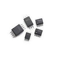
ACPL-M61L-060E Avago Technologies US Inc., ACPL-M61L-060E Datasheet - Page 8

ACPL-M61L-060E
Manufacturer Part Number
ACPL-M61L-060E
Description
OPTOCOUPLER 10MBD ULP 5-SOIC
Manufacturer
Avago Technologies US Inc.
Series
R²Coupler™r
Datasheet
1.ACPL-M61L-500E.pdf
(17 pages)
Specifications of ACPL-M61L-060E
Package / Case
6-SOIC (0.173", 4.40mm Width) 5 Leads
Voltage - Isolation
3750Vrms
Number Of Channels
1, Unidirectional
Current - Output / Channel
10mA
Data Rate
10MBd
Propagation Delay High - Low @ If
46ns @ 6.5mA
Current - Dc Forward (if)
8mA
Input Type
DC
Output Type
Push-Pull, Totem-Pole
Mounting Type
Surface Mount
Isolation Voltage
3750 Vrms
Maximum Fall Time
12 ns
Maximum Rise Time
12 ns
Output Device
Logic Gate Photo IC
Configuration
1 Channel
Maximum Baud Rate
10 MBps
Maximum Forward Diode Voltage
6.5 V
Maximum Reverse Diode Voltage
5 V
Maximum Power Dissipation
20 mW
Maximum Operating Temperature
+ 105 C
Minimum Operating Temperature
- 40 C
No. Of Channels
1
Optocoupler Output Type
Logic Gate
Input Current
150mA
Output Voltage
7V
Opto Case Style
SOIC
No. Of Pins
5
Peak Reflow Compatible (260 C)
Yes
Rohs Compliant
Yes
Number Of Elements
1
Forward Voltage
1.7V
Forward Current
8mA
Output Current
10mA
Operating Temp Range
-40C to 105C
Pin Count
5
Mounting
Surface Mount
Reverse Breakdown Voltage
5V
Operating Temperature Classification
Industrial
Leaded Process Compatible
Yes
Lead Free Status / RoHS Status
Lead free / RoHS Compliant
Lead Free Status / RoHS Status
Lead free / RoHS Compliant, Lead free / RoHS Compliant
Available stocks
Company
Part Number
Manufacturer
Quantity
Price
Part Number:
ACPL-M61L-060E
Manufacturer:
AVAGO/安华高
Quantity:
20 000
Switching Specifications (AC)
Over the recommended temperature (T
fications are at V
8
Parameter
Propagation Delay Time
to Logic Low Output
Propagation Delay Time
to Logic High Output
Pulse Width
Pulse Width Distortion
Propagation Delay Skew
Output Rise Time
(10% – 90%)
Output Fall Time
(90% - 10%)
Propagation Delay Time
of Enable from V
Propagation Delay Time
of Enable from V
Static Common Mode
Transient Immunity at
Logic High Output
Static Common Mode
Transient Immunity at
Logic Low Output
Dynamic Common Mode
Transient Immunity
EH
EL
DD
[5]
[4]
to V
to V
[6]
[1]
= 5 V, T
[1]
[2]
EH
EL
[3]
A
Symbol
t
t
t
PWD
t
t
t
T
T
| CM
| CM
CMR
= 25°C.
PHL
PLH
PW
PSK
R
F
ELH
EHL
H
L
D
|
|
ACPL-061L
ACPL-061L
Number
Part
A
All
All
All
All
All
All
All
All
All
All
= –40°C to +105°C) and supply voltage (2.7 V ≤ V
100
Min
20
20
Typ
46
40
12
10
12
10
12
35
35
35
6
9
Max
80
80
30
30
Units
ns
ns
ns
ns
ns
ns
ns
ns
ns
ns
ns
kV/Ps
kV/Ps
kV/Ps
Test Conditions
I
C
I
C
Figure 11
I
C
Figure 11
I
C
Figure 11
I
C
Figure 11
I
C
Figure 11
V
V
C
Figure 11
V
(R
(R
CMOS Signal Levels.
Figure 11
V
V
(R
absolute increase of PWD < 10ns
Figure 11
V
F
F
F
F
F
F
L
L
L
L
L
L
EL
CM
L
CM
CM
I
I
= 2 mA, V
= 2 mA, V
= 2 mA, V
T
T
T
= 5 V (R
= 2 mA, V
= 2 mA, V
= 2 mA, V
= 15 pF, CMOS Signal Levels.
= 15 pF, CMOS Signal Levels.
= 15 pF, CMOS Signal Levels.
= 15 pF, CMOS Signal Levels.
= 15 pF, CMOS Signal Levels.
= 15 pF, CMOS Signal Levels.
= 0 V (R
= 15 pF, CMOS Signal Levels.
=0, V
= 870:), I
= 870:), 10MBd datarate, the
= 1.68 k:) or V
= 1000 V, T
= 1000 V, T
= 1000 V, T
DD
EH
T
T
=3V, C
≤ 5.5 V). All typical speci-
= 1.68 k:) or V
I
I
I
=1.68 k:) or (R
I
I
I
= 3.3 V, R
= 3.3 V, R
= 3.3 V, R
= 5 V, R
= 5 V, R
= 5 V, R
F
= 2 mA, C
A
A
A
L
= 25°C, I
= 25°C, V
= 25°C, I
= 15pF
I
= 3.3 V
T
T
T
T
T
T
= 1.68 k:,
= 1.68 k:,
= 1.68 k:,
= 870 :,
= 870 :,
= 870 :,
L
F
F
= 15 pF,
I
I
= 0 mA,
= 2 mA,
= 5 V
T
= 3.3 V
= 870:),


