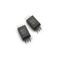
ACPL-W60L-500E Avago Technologies US Inc., ACPL-W60L-500E Datasheet

ACPL-W60L-500E
Specifications of ACPL-W60L-500E
Related parts for ACPL-W60L-500E
ACPL-W60L-500E Summary of contents
Page 1
... HIE 0.1 μF bypass capacitor must be connected between pins 4 and 6 for ACPL-W60L and pins 5 and 8 for ACPL-K63L. CAUTION advised that normal static precautions be taken in handling and assembly of this component to prevent damage and/or degradation which may be induced by ESD. Features x Dual Voltage Operation (3.3V/5V) ...
Page 2
... To order, choose a part number from the part number column and combine with the desired option from the option column to form an order entry. Example 1: ACPL-W60L-560E to order product of Stretched SO-6 Surface Mount package in Tape and Reel packaging with IEC/EN/DIN EN 60747-5-2 Safety Approval in RoHS compliant. Option datasheets are available. Contact your Avago sales representative or authorized distributor for information. ...
Page 3
... ACPL-K63L Stretched S - Package 0.3 1 ± 0.13 0.01 ± 0. ° 0.01 ° ± 0.100 0.00 ± 0. ± 0 ± 0. ± 0.0 9 ± 0.010 11. ± ± 0.010 3 1. ...
Page 4
... THE TIME FROM 25 °C to PEAK TEMPERATURE = 8 MINUTES MAX 200 ° 150 °C smax smin Note: Non-halide flux should be used. egulatory Information The ACPL-W60L/K63L have been approved by the following organizations: L Approval under UL 1577, Component Recognition Program, File E55361. CSA Approval under CSA Component Acceptance Notice #5, File CA 88324 / ...
Page 5
Insulation and Safety elated Specifications Parameter Symbol Minimum External Air L (101) Gap (External Clearance) Minimum External Tracking L (102) (External Creepage) Minimum Internal Plastic Gap (Internal Clearance) Tracking Resistance CTI (Comparative Tracking Index) Isolation Group I C/ /DI 60 ...
Page 6
Absolute Maximum atings o Derating equired up to ˚C Parameter Storage Temperature Operating Temperature† Average Forward Input Current Reverse Input Voltage Input Power Dissipation Supply Voltage (1 Minute Maximum) Output Collector Current Output Collector Voltage Output Power Dissipation Solder Reflow ...
Page 7
Specifications Over Recommended Operating Conditions (T All Typicals 3 25˚ Parameter Sym. Device High Level Output Current Input Threshold I TH Current Low Level Output ...
Page 8
Switching Specifications Over Recommended Temperature (T All Typicals 25˚ 3 Parameter Sym. Propagation Delay t PLH Time to High Output Level Propagation Delay t PHL Time to Low Output Level Pulse Width ...
Page 9
... ACPL-W60L H Level Common ACPL-K63L Mode Transient Immunity Output Low |CM | ACPL-W60L L Level Common ACPL-K63L Mode Transient Immunity Output High |CM | ACPL-W60L H Level Common ACPL-K63L Mode Transient Immunity Output Low |CM | ACPL-W60L L Level Common ACPL-K63L Mode Transient Immunity 9 Min. Typ. nits Test Conditions 15 25 kV/ ...
Page 10
Package Characteristics All Typicals 25˚C. A Parameter Sym. Package Input-Output I * Single I-O Insulation Input-Output V Single, ISO Momentary Dual Channel Withstand Voltage* Input-Output R Single, I-O Resistance Dual Channel Input-Output C Single, I-O Capacitance Dual ...
Page 11
250 μA = 250 μ -60 -60 ...
Page 12
-60 -40 - – TEMPERATURE – °C A Figure . Typical low level output ...
Page 13
350 Ω -60 -40 - 100 60 T – TEMPERATURE – Figure . Typical pulse ...


