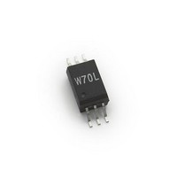
ACPL-W70L-520E Avago Technologies US Inc., ACPL-W70L-520E Datasheet

ACPL-W70L-520E
Specifications of ACPL-W70L-520E
Related parts for ACPL-W70L-520E
ACPL-W70L-520E Summary of contents
Page 1
... SSOIC-8 package respectively. The optocouplers utilize the latest CMOS IC technology to achieve outstanding perfor- mance with very low power consumption. Basic building blocks of ACPL-W70L and ACPL-K73L are high speed LEDs and CMOS detector ICs. Each detector incorporates an in- tegrated photodiode, a high speed transimpedance am- plifi ...
Page 2
... To order, choose a part number from the part number column and combine with the desired option from the option column to form an order entry. Example 1: ACPL-W70L-500E to order product of stretched SO-6 package in Tape and Reel packaging in RoHS compliant. Option datasheets are available. Contact your Avago sales representative or authorized distributor for information. 2 for 1 minute per UL1577 ...
Page 3
... ACPL-K73L (Stretched S0-8 Package) 0.381 0.13 (0.015 0.005 0.450 (0.018) 45 0.200 0.100 (0.008 0.004) 6.807 0.127 (0.268 0.005) 0.750 0.250 (0.0295 0.010) 11 ...
Page 4
... SOLDERING 30 SEC. 30 SEC. 50 SEC. 100 150 TIME (SECONDS) Regulatory Information The ACPL-W70L and ACPL-K73L are approved by the fol- lowing organizations 20-40 SEC. UL Recognized under UL 1577, component recognition pro- gram, File E55361. RAMP-DOWN 6 °C/SEC. MAX. CSA Approved under CSA Component Acceptance Notice #5, File CA88324 ...
Page 5
Parameter Symbol Minimum External Air L(I01) Gap (Clearance) Minimum External L(I02) Tracking (Creepage) Minimum Internal Plastic Gap (Internal Clearance) Tracking Resistance CTI (Comparative Tracking Index) Isolation Group All Avago Technologies data sheets report the creepage and clearance inherent to the ...
Page 6
... Logic High Output V OH Voltage Logic Low Output V OL Voltage Input Threshold I TH Current Logic Low Output I ACPL-W70L DDL Supply Current ACPL-K73L Logic Low Output I ACPL-W70L DDH Supply Current ACPL-K73L 6 Symbol Min. T – – –0 260°C for 10 sec., 1.6 mm below seating plane See Solder Refl ...
Page 7
Switching Specifications Over recommended temperature (T All typical specifications are at T =+25° Parameter Propagation Delay Time [2] to Logic Low Output Propagation Delay Time [2] to Logic High Output Pulse Width [3] Pulse Width Distortion [4] Propagation ...
Page 8
... Figure 2. Typical input threshold current vs. temperature = =3. 100 -40 Figure 4. Typical logic low output supply current vs. temperature for dual channel (ACPL-K73L CH1 PHL CH1 15 PLH 10 |PWD| CH2 Figure 6. Typical switching speed vs. pulse input current at 3.3V supply voltage I ...
Page 9
... F Application Information Bypassing and PC Board Layout The ACPL-W70L and ACPL-K73L optocouplers are ex- tremely easy to use. ACPL-W70L and ACPL-K73L provide CMOS logic output due to the high-speed CMOS IC tech- nology used. The external components required for proper operation are the input limiting resistor and the output bypass ca- pacitor. Capacitor values should be between 0.01 μ ...
Page 10
... GND 1 Vo GND ACPL-K73L C=0.01μF to 0.1μF DATA INPUTS CLOCK DATA OUTPUTS CLOCK 2.5 V, CMOS Figure 10. Parallel data transmission example. Figure 10 shows that there will be uncertainty in both the data and the clock lines important that these two ar- can de- eas of uncertainty not overlap, otherwise the clock signal ...
Page 11
... To limit the amount of current flowing through the LED recommended that a 530ohm resistor is connected in series with anode of LED (i.e. Pin 1 for ACPL-W70L, Pin 1 and P4 for ACPL-K73L input signal. At 3.3V input signal recommended to connect 250ohm resistor in series with anode of LED ...
Page 12
... I is close to the switching threshold ( also depends on the extent which I L 1/2R V DD1 1/2R 74LS04 OR ANY TOTEM- POLE OUTPUT LOGIC GATE GND 1 Figure 13. Recommended drive circuit for ACPL-W70L and ACPL-K73L for high-CMR ½ R total ½ R total SHIELD Figure 14. AC equivalent of ACPL-W70L and ACPL-K73L 12 each other ...
Page 13
... FH recommendation. Using any one of the drive circuits in Figures 15-17 with will result in a typical CMR of 10 kV/μs for ACPL- F W70L AND ACPL-K73L, as long as the PC board layout practices are followed. Figure 15 shows a circuit which can be used with any totem-pole-output TTL/LSTTL/HCMOS logic gate. The buffer PNP transistor allows the circuit to be used with logic devices which have low current-sinking capability ...
Page 14
R limit SHIELD + Pulse Gen SWITCH (min.) SWITCH ...


