ACPL-4800-300E Avago Technologies US Inc., ACPL-4800-300E Datasheet
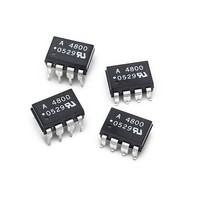
OPTOCOUPLER IPM 5MBD 8-SMD GW

ACPL-4800-300E

Manufacturer Part Number
ACPL-4800-300E
Description
OPTOCOUPLER IPM 5MBD 8-SMD GW
Manufacturer
Avago Technologies US Inc.
Datasheet

Specifications of ACPL-4800-300E

Output Type
Push-Pull, Totem-Pole
Package / Case
8-SMD Gull Wing
Voltage - Isolation
3750Vrms
Number Of Channels
1, Unidirectional
Current - Output / Channel
25mA
Data Rate
5MBd
Propagation Delay High - Low @ If
150ns @ 10mA
Current - Dc Forward (if)
10mA
Input Type
DC
Mounting Type
Surface Mount, Gull Wing
Fall Time
20 ns
Logic Gate Type
AND Schmitt
Maximum Baud Rate
5 MBps
Rise Time
16 ns
Configuration
1 Channel
Isolation Voltage
3750 Vrms
Maximum Propagation Delay Time
350 ns
Maximum Forward Diode Voltage
1.7 V
Maximum Forward Diode Current
10 mA
Maximum Operating Temperature
+ 100 C
Minimum Operating Temperature
- 40 C
Lead Free Status / RoHS Status
Lead free / RoHS Compliant

Available stocks

Company
Part Number
Manufacturer
Quantity
Price
Part Number:
ACPL-4800-300E
Manufacturer:
AVAGO
Quantity:
3 000
Part Number:
ACPL-4800-300E
Manufacturer:
AVAGO/安华高
Quantity:
20 000
ACPL-4800
High CMR Intelligent Power Module and
Gate Drive Interface Optocoupler
Data Sheet
Description
The ACPL-4800 fast speed optocoupler contains a GaAsP
LED and photo detector with built-in Schmitt trigger to
provide logic-compatible waveforms, eliminating the need
for additional wave shaping. The totem pole output elimi-
nates the need for a pull up resistor and allows for direct
drive Intelligent Power Module or gate drive.
Functional Diagram
Schematic
V
+
-
RoHS 6 fully compliant options available;
-xxxE denotes a lead-free product
F
3
2
I
F
Lead (Pb) Free
RoHS 6 fully
compliant
SHIELD
CATHODE
Note: The connection of a 0.1 µF
bypass capacitor between pins 5
& 8 is recommended.
ANODE
CAUTION: It is advised that normal static precautions be taken in handling and assembly
of this component to prevent damage and /or degradation which may be induced by ESD.
NC
NC
1
2
3
4
(POSITIVE LOGIC)
SHIELD
LED
OFF
TRUTH TABLE
ON
HIGH
LOW
V
O
8
7
6
5
I
V
NC
V
GND
CC
I
O
CC
O
8
5
6
V
V
GND
CC
O
Features
• Performance Specified for Fast IPM Applications over
• Wide Operating V
• Typical Propagation Delays 150 ns
• Maximum Pulse Width Distortion
• Propagation Delay Difference
• 30 kV/µs Minimum Common Mode Transient Immunity
• Hysteresis
• Totem Pole Output (No Pull-up Resistor Required)
• Safety Approval:
Applications
• IPM Interface Isolation
• Isolated IGBT/MOSFET Gate Drive
• AC and Brushless DC Servo Motor Drives
• Low Power Inverters
• General Digital Isolation
Industrial Temperature Range: -40°C to 100°C
PWD = 250 ns
Min. –100 ns, Max. 250 ns
at V
CM
UL 1577, 3750 V
CSA File CA88324, Notice #5
IEC/EN/DIN EN 60747-5-2, V
= 1000 V
CC
Range: 4.5 to 20 Volts
rms
/ 1 minute
IORM
= 630 V
peak

Related parts for ACPL-4800-300E

ACPL-4800-300E Summary of contents

Page 1

... RoHS 6 fully compliant options available; -xxxE denotes a lead-free product Description The ACPL-4800 fast speed optocoupler contains a GaAsP LED and photo detector with built-in Schmitt trigger to provide logic-compatible waveforms, eliminating the need for additional wave shaping. The totem pole output elimi- nates the need for a pull up resistor and allows for direct drive Intelligent Power Module or gate drive ...

Page 2

... Ordering Information ACPL-4800 is UL Recognized with 3750 Vrms for 1 minute per UL1577 and is approved under CSA Component Acceptance Notice #5, File CA 88324. Option RoHS Part number Compliant Package -000E -300E -500E ACPL-4800 300mil DIP-8 -060E -360E -560E To order, choose a part number from the part number column and combine with the desired option from the option column to form an order entry ...

Page 3

DIP-8 Package with Gull Wing Surface Mount Option 300 9.65 ± 0.25 (0.380 ± 0.010 1.19 (0.047) MAX. 1.080 ± 0.320 (0.043 ± 0.013) 2.54 (0.100) BSC DIMENSIONS IN MILLIMETERS (INCHES). LEAD COPLANARITY = ...

Page 4

Solder Reflow Temperature Profile (Gull Wing Surface Mount Option 300 Parts) 300 PREHEATING RATE 3˚C + 1˚C/-0.5˚C/SEC. REFLOW HEATING RATE 2.5˚C ± 0.5˚C/SEC. 200 160˚C 150˚C 140˚C 100 ROOM TEMPERATURE Note: Non-halide flux should be used Recommended ...

Page 5

Insulation and Safety Related Specifications Parameter Symbol Minimum External Air L(101) Gap(External Clearance) Minimum External Track- L(102) ing (External Creepage) Minimum Internal Plastic Gap (Internal Clearance) Minimum Internal Tracking (Internal Creepage) Tracking Resistance CTI (Comparative Tracking Index) Isolation Group Option ...

Page 6

Thermal Derating Curve 800 P (mW) S 700 I (mA) S 600 500 400 300 200 100 100 125 150 175 - CASE TEMPERATURE - Absolute Maximum Rating Parameter Storage Temperature ...

Page 7

Electrical Specification -40°C ≤ T ≤ 100°C, 4.5V ≤ V ≤ 20V, 6mA ≤ All Typicals 25°C. A Parameter Sym. Logic Low V OL Output Voltage Logic High V OH Output Voltage Output Leakage ...

Page 8

Switching Specifications (AC) -40°C ≤ T ≤ 100°C, 4.5V ≤ V ≤ 20V, 6mA ≤ All Typicals 25° unless otherwise specified. A F(ON) Parameter Sym. Propagation Delay Time t PHL ...

Page 9

V = 4.5/20V 0. 6.4mA 0.12 0.11 0.1 - TEMPERATURE - ˚C A Figure 1. Typical Logic Low Output Voltage ...

Page 10

PHL 170 150 130 t PLH 110 -60 -40 - TEMPERATURE - C A Figure 6. Typical Propagation Delays vs.Temperature. 200 180 160 t PHL 140 120 100 ...

Related keywords