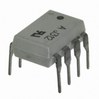
HCPL-J312-000E Avago Technologies US Inc., HCPL-J312-000E Datasheet - Page 22

HCPL-J312-000E
Manufacturer Part Number
HCPL-J312-000E
Description
OPTOCOUPLER 1CH 2.5A 8-DIP
Manufacturer
Avago Technologies US Inc.
Datasheet
1.HCPL-3120-500E.pdf
(24 pages)
Specifications of HCPL-J312-000E
Output Type
Gate Driver
Package / Case
8-DIP (0.300", 7.62mm)
Voltage - Isolation
3750Vrms
Number Of Channels
1, Unidirectional
Current - Output / Channel
2.5A
Propagation Delay High - Low @ If
300ns @ 7mA ~ 16mA
Current - Dc Forward (if)
16mA
Input Type
DC
Mounting Type
Through Hole
Configuration
1 Channel
Isolation Voltage
3750 Vrms
Maximum Propagation Delay Time
500 ns
Maximum Forward Diode Voltage
1.95 V
Minimum Forward Diode Voltage
1.2 V
Maximum Reverse Diode Voltage
3 V
Maximum Forward Diode Current
25 mA
Maximum Power Dissipation
295 mW
Maximum Operating Temperature
+ 100 C
Minimum Operating Temperature
- 40 C
No. Of Channels
1
Optocoupler Output Type
Gate Drive
Input Current
16mA
Output Voltage
30V
Opto Case Style
DIP
No. Of Pins
8
Common Mode Ratio
15 KV/uS
Rohs Compliant
Yes
Lead Free Status / RoHS Status
Lead free / RoHS Compliant
Lead Free Status / RoHS Status
Lead free / RoHS Compliant, Lead free / RoHS Compliant
Other names
516-1879-5
HCPL-J312-000E
HCPL-J312-000E
Available stocks
Company
Part Number
Manufacturer
Quantity
Price
Company:
Part Number:
HCPL-J312-000E
Manufacturer:
AVAGO
Quantity:
2 000
Part Number:
HCPL-J312-000E
Manufacturer:
AVAGO/安华高
Quantity:
20 000
+5 V
CMR with the LED On (CMR
A high CMR LED drive circuit must keep the LED on during
common mode transients. This is achieved by overdriv-
ing the LED current beyond the input threshold so that
it is not pulled below the threshold during a transient.
A minimum LED current of 10 mA provides adequate
margin over the maximum I
µs CMR.
CMR with the LED Off (CMR
A high CMR LED drive circuit must keep the LED off
(V
example, during a -dV
current flowing through C
Figure 31. Equivalent circuit for figure 25 during common mode transient.
Figure 33. Recommended LED drive circuit for ultra-high CMR.
22
F
+5 V
≤ V
F(OFF)
V
+
–
SAT
) during common mode transients. For
1
2
3
4
* THE ARROWS INDICATE THE DIRECTION
OF CURRENT FLOW DURING –dV
1
2
3
4
C
C
LEDP
LEDN
HCPL-3120 fig 33
SHIELD
C
C
I
LEDP
LEDP
LEDN
cm
SHIELD
HCPL-3120 fig 31
/dt transient in Figure 31, the
H
L
).
).
LEDP
V
FLH
+
CM
–
of 5 mA to achieve 25 kV/
also flows through the
8
7
6
5
CM
/dt.
8
7
6
5
0.1
µF
+
–
Rg
V
CC
R
voltage developed across the logic gate is less than
V
failure will occur.
The open collector drive circuit, shown in Figure 32,
cannot keep the LED off during a +dVcm/dt transient,
since all the current flowing through C
supplied by the LED, and it is not recommended for
applica-tions requiring ultra high CMR
Figure 33 is an alternative drive circuit which, like the rec-
ommended applica-tion circuit (Figure 25), does achieve
ultra high CMR performance by shunting the LED in the
off state.
= 18 V
SAT
F(OFF)
• • •
• • •
and V
, the LED will remain off and no common mode
+5 V
Figure 34. Under voltage lock out.
Q1
Figure 32. Not recommended open collector drive circuit.
SAT
14
12
10
8
6
4
2
0
of the logic gate. As long as the low state
0
(V
CC
- V
1
2
3
4
EE
(10.7, 0.1)
5
(10.7, 9.2)
HCPL-3120 fig 34
) – SUPPLY VOLTAGE – V
C
C
I
LEDN
LEDN
LEDP
HCPL-3120 fig 32
SHIELD
10
(12.3, 0.1)
(12.3, 10.8)
15
L
performance.
20
LEDN
8
7
6
5
must be


