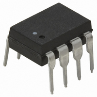
HCPL-263N Avago Technologies US Inc., HCPL-263N Datasheet - Page 12

HCPL-263N
Manufacturer Part Number
HCPL-263N
Description
OPTOCPLR LOG-OUT 2CH 10MBD 8-DIP
Manufacturer
Avago Technologies US Inc.
Datasheet
1.HCPL-061A-000E.pdf
(17 pages)
Specifications of HCPL-263N
Voltage - Isolation
3750Vrms
Number Of Channels
2, Unidirectional
Current - Output / Channel
50mA
Data Rate
10MBd
Propagation Delay High - Low @ If
53ns @ 3.5mA
Current - Dc Forward (if)
10mA
Input Type
DC
Output Type
Open Collector
Mounting Type
Through Hole
Package / Case
8-DIP (0.300", 7.62mm)
No. Of Channels
2
Isolation Voltage
3.75kV
Optocoupler Output Type
Logic Gate
Input Current
10mA
Output Voltage
7V
Opto Case Style
DIP
No. Of Pins
8
Propagation Delay Low-high
100ns
Common Mode Voltage Vcm
1000V
Lead Free Status / RoHS Status
Contains lead / RoHS non-compliant
Other names
516-1096-5
Available stocks
Company
Part Number
Manufacturer
Quantity
Price
Company:
Part Number:
HCPL-263N
Manufacturer:
AVAGO
Quantity:
8 000
Company:
Part Number:
HCPL-263N-000E
Manufacturer:
AVAGO
Quantity:
3 100
Company:
Part Number:
HCPL-263N-000E
Manufacturer:
AVAGO
Quantity:
8 000
Company:
Part Number:
HCPL-263N-020E
Manufacturer:
AVAGO
Quantity:
20 000
Company:
Part Number:
HCPL-263N-300E
Manufacturer:
AVAGO
Quantity:
8 000
Part Number:
HCPL-263N-520E
Manufacturer:
AVAGO/安华高
Quantity:
20 000
Figure 13. Typical pulse width distortion vs.
temperature.
12
Figure 10. Typical input threshold current vs.
temperature.
2.0
1.5
1.0
0.5
60
50
40
30
20
10
0
0
-60
-60
-40
-40
R
R
R
R
T
T
L
A
A
L
L
L
-20
-20
= 1 kΩ
= 350 Ω
= 1 kΩ
= 4 kΩ
– TEMPERATURE – C
– TEMPERATURE – C
HCPL-261A fig 10
HCPL-261A fig 13
R
L
0
0
= 4 kΩ
20
20
40
40
R
V
V
V
I
L
F
CC
O
CC
60
= 350 Ω
60
= 3.5 mA
= 0.6 V
= 5 V
= 5 V
80
80
100
100
Figure 11. Typical propagation delay vs. tem-
perature.
Figure 14. Typical rise and fall time vs. temperature.
160
140
120
120
100
60
40
20
80
60
40
20
0
0
-60
-60
V
I
F
CC
-40
-40
= 3.5 mA
TPLH
R
TPLH
R
TPLH
R
T
= 5 V
T
L
L
L
A
A
-20
-20
= 4 kΩ
= 1 kΩ
= 350 kΩ
– TEMPERATURE – C
– TEMPERATURE – C
HCPL-261A fig 14
HCPL-261A fig 11
R
R
R
R
L
L
L
L
0
0
= 1 kΩ
= 350 Ω
= 350 Ω, 1 kΩ, 4 kΩ
= 4 kΩ
TPHL
R
L
20
20
= 350 Ω, 1 kΩ, 4 kΩ
V
I
F
CC
40
40
= 3.5 mA
= 5 V
60
60
t
t
rise
fall
80
80
100
100
Figure 12. Typical propagation delay vs. pulse
input current.
120
100
80
60
40
20
0
0
TPLH
R
I
L
F
= 4 kΩ
– PULSE INPUT CURRENT – mA
2
TPHL
R L = 350 Ω, 1 kΩ, 4 kΩ
HCPL-261A fig 12
4
V
T
CC
A
= 25 C
= 5 V
6
8
TPLH
R
TPLH
R
L
L
= 350 Ω
10
= 1 kΩ
12


