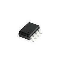
HCPL-263N#300 Avago Technologies US Inc., HCPL-263N#300 Datasheet - Page 15

HCPL-263N#300
Manufacturer Part Number
HCPL-263N#300
Description
OPTOCOUPLER 2CH 10MBD 8-SMD GW
Manufacturer
Avago Technologies US Inc.
Datasheet
1.HCPL-061A-000E.pdf
(17 pages)
Specifications of HCPL-263N#300
Package / Case
8-SMD Gull Wing
Voltage - Isolation
3750Vrms
Number Of Channels
2, Unidirectional
Current - Output / Channel
50mA
Data Rate
10MBd
Propagation Delay High - Low @ If
53ns @ 3.5mA
Current - Dc Forward (if)
10mA
Input Type
DC
Output Type
Open Collector
Mounting Type
Surface Mount, Gull Wing
Isolation Voltage
3750 Vrms
Maximum Continuous Output Current
50 mA
Maximum Fall Time
12 ns
Maximum Forward Diode Current
10 mA
Maximum Rise Time
42 ns
Minimum Forward Diode Voltage
1 V
Output Device
Logic Gate Photo IC
Configuration
2 Channel
Maximum Baud Rate
10 MBps
Maximum Forward Diode Voltage
1.6 V
Maximum Reverse Diode Voltage
3 V
Maximum Power Dissipation
60 mW
Maximum Operating Temperature
+ 85 C
Minimum Operating Temperature
- 40 C
Lead Free Status / RoHS Status
Contains lead / RoHS non-compliant
Available stocks
Company
Part Number
Manufacturer
Quantity
Price
15
Table 1 indicates the directions of I
ing on the direction of the common-mode transient.
For transients occurring when the LED is on, common-
mode rejection (CMR
state) depends upon the amount of LED current drive (I
For conditions where I
old (I
balance each other. In other words, any condition where
common-mode transients cause a momentary decrease
in I
1) will cause common-mode failure for transients which
are fast enough.
Likewise for common-mode transients which occur
when the LED is off (i.e. CMR
if an imbalance between I
I
optocoupler, the transient “signal” may cause the output
to spike below 2 V (which constitutes a CMR
By using the recommended circuit in Figure 20, good
CMR can be achieved. (In the case of the -261N families,
a minimum CMR of 15 kV/µs is guaranteed using this cir-
cuit.) The balanced I
and I
from transient coupling through C
Figure 21. AC equivalent circuit for HCPL-261X.
F
1/2 R
1/2 R
equal to or greater than the switching threshold of the
F
(i.e. when dV
TH
LN
LED
LED
), CMR
to reduce the amount by which I
1
2
3
4
L
also depends on the extent which I
I
LN
CM
SHIELD
/dt>0 and |I
LED
+
I
C
LP
HCPL- 261A fig 20
L
V
LC
, since the output is in the “low”
F
-setting resistors help equalize I
CM
C
is close to the switching thresh-
LA
–
LP
H
and I
, since the output is “high”),
FP
| > |I
LN
LP
LA
8
7
6
5
results in a transient
and I
FN
and C
|, referring to Table
LED
LN
0.01 µF
LC
flow depend-
is modulated
.
H
failure).
15 pF
LP
350 Ω
and I
F
LN
LP
).
V
V
GND
CC
O
CMR with Other Drive Circuits
CMR performance with drive circuits other than that
shown in Figure 20 may be enhanced by following these
guidelines:
1. Use of drive circuits where current is shunted from
2. Use of I
Using any one of the drive circuits in Figures 22-24 with
I
HCPL-261N family, as long as the PC board layout prac-
tices are followed. Figure 22 shows a circuit which can
be used with any totem-pole-output TTL/LSTTL/HCMOS
logic gate. The buffer PNP transistor allows the circuit to
be used with logic devices which have low current-sink-
ing capability. It also helps maintain the driving-gate
power-supply current at a constant level to minimize
ground shifting for other devices connected to the in-
put-supply ground.
When using an open-collector TTL or open-drain CMOS
logic gate, the circuit in Figure 23 may be used. When
using a CMOS gate to drive the optocoupler, the circuit
shown in Figure 24 may be used. The diode in parallel
with the R
LED.
+
F
= 10 mA will result in a typical CMR of 8 kV/µs for the
the LED in the LED “off” state (as shown in Figures 22
and 23). This is beneficial for good CMR
TTL/CMOS
Figure 22. TTL interface circuit for the HCPL-261A/-261N families.
74L504
FH
GATE)
LED
(ANY
> 3.5 mA. This is good for high CMR
speeds the turn-off of the optocoupler
V
HCPL- 261A fig 21
CC
2N3906
(ANY PNP)
420 Ω
(MAX)
1
2
3
4
H
.
HCPL-261X
LED
L
.


