BFC237021823 Vishay, BFC237021823 Datasheet - Page 8
BFC237021823
Manufacturer Part Number
BFC237021823
Description
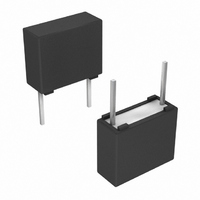
CAP FILM MKT .082UF 100VDC 10%
Manufacturer
Vishay
Series
MKT 370r
Datasheet
1.BFC237016104.pdf
(18 pages)
Specifications of BFC237021823
Capacitance
0.082µF
Voltage - Ac
63V
Voltage - Dc
100V
Dielectric Material
Polyester, Metallized
Tolerance
±10%
Operating Temperature
-55°C ~ 105°C
Mounting Type
Through Hole
Package / Case
Radial
Size / Dimension
0.284" L x 0.098" W (7.20mm x 2.50mm)
Height
0.256" (6.50mm)
Termination
PC Pins
Lead Spacing
0.200" (5.08mm)
Features
General Purpose
Voltage Rating
100 Volts
Termination Style
Radial
Product
Metallized Polyester Film Capacitors
Dimensions
2.5 mm W x 7.2 mm L x 6.5 mm H
Operating Temperature Range
0 C to + 85 C
Dissipation Factor Df
75
Lead Free Status / RoHS Status
Contains lead / RoHS non-compliant
Esr (equivalent Series Resistance)
-
Lead Free Status / Rohs Status
Lead free / RoHS Compliant
Other names
2222 370 21823
222237021823
BC1658
BFC2 370 21823
BFC2 370 21823
222237021823
BC1658
BFC2 370 21823
BFC2 370 21823


MKT370
DC Film Capacitors
Vishay BCcomponents
MKT Radial Potted Type
MOUNTING
Normal Use
The capacitors are designed for mounting on printed-circuit boards. The capacitors packed in bandoliers are designed for
mounting in printed-circuit boards by means of automatic insertion machines.
For detailed tape specifications refer to packaging information:
www.vishay.com/doc?28139
or end of catalog.
Specific Method of Mounting to Withstand Vibration and Shock
In order to withstand vibration and shock tests, it must be ensured that stand-off pips are in good contact with the printed-circuit
board:
• For pitches ≤ 15 mm capacitors shall be mechanically fixed by the leads
• For larger pitches the capacitors shall be mounted in the same way and the body clamped
Space Requirements on Printed Circuit Board
The maximum space for length (I
), width (w
) and heigth (h
) of film capacitors to take in account on the printed circuit
max.
max.
max.
board is shown in the drawings.
• For products with pitch ≤ 15 mm, Δw = Δl = 0.3 mm; Δh = 0.1 mm
Eccentricity defined as in drawing. The maximum eccentricity is smaller than or equal to the lead diameter of the product
concerned.
= W + Δ
w
max.
Eccentricity
= I + Δ
I
CBA116
max.
= h + Δ
h
max.
Seating plane
SOLDERING CONDITIONS
For general soldering conditions and wave soldering profile, we refer to the application note:
“Soldering Guidelines for Film Capacitors”:
www.vishay.com/doc?28171
Storage Temperature
• Storage temperature: T
= - 25 °C to + 40 °C with RH maximum 80 % without condensation
stg
Ratings and Characteristics Reference Conditions
Unless otherwise specified, all electrical values apply to an ambient temperature of 23 °C ± 1 °C, an atmospheric pressure of
86 kPa to 106 kPa and a relative humidity of 50 % ± 2 %.
For reference testing, a conditioning period shall be applied over 96 h ± 4 h by heating the products in a circulating air oven at
the rated temperature and a relative humidity not exceeding 20 %.
www.vishay.com
For technical questions, contact:
dc-film@vishay.com
Document Number: 28108
84
Revision: 22-Dec-10
Related parts for BFC237021823
Image
Part Number
Description
Manufacturer
Datasheet
Request
R

Part Number:
Description:
357-036-542-201 CARDEDGE 36POS DL .156 BLK LOPRO
Manufacturer:
Vishay
Datasheet:
Part Number:
Description:
357-036-542-201 CARDEDGE 36POS DL .156 BLK LOPRO
Manufacturer:
Vishay
Datasheet:
Part Number:
Description:
357-036-542-201 CARDEDGE 36POS DL .156 BLK LOPRO
Manufacturer:
Vishay
Datasheet:
Part Number:
Description:
357-036-542-201 CARDEDGE 36POS DL .156 BLK LOPRO
Manufacturer:
Vishay
Datasheet:
Part Number:
Description:
357-036-542-201 CARDEDGE 36POS DL .156 BLK LOPRO
Manufacturer:
Vishay
Datasheet:
Part Number:
Description:
357-036-542-201 CARDEDGE 36POS DL .156 BLK LOPRO
Manufacturer:
Vishay
Datasheet:
Part Number:
Description:
357-036-542-201 CARDEDGE 36POS DL .156 BLK LOPRO
Manufacturer:
Vishay
Datasheet:
Part Number:
Description:
357-036-542-201 CARDEDGE 36POS DL .156 BLK LOPRO
Manufacturer:
Vishay
Datasheet:
Part Number:
Description:
357-036-542-201 CARDEDGE 36POS DL .156 BLK LOPRO
Manufacturer:
Vishay
Datasheet:
Part Number:
Description:
357-036-542-201 CARDEDGE 36POS DL .156 BLK LOPRO
Manufacturer:
Vishay
Datasheet:
Part Number:
Description:
357-036-542-201 CARDEDGE 36POS DL .156 BLK LOPRO
Manufacturer:
Vishay
Datasheet:
Part Number:
Description:
357-036-542-201 CARDEDGE 36POS DL .156 BLK LOPRO
Manufacturer:
Vishay
Datasheet:
Part Number:
Description:
357-036-542-201 CARDEDGE 36POS DL .156 BLK LOPRO
Manufacturer:
Vishay
Datasheet:
Part Number:
Description:
357-036-542-201 CARDEDGE 36POS DL .156 BLK LOPRO
Manufacturer:
Vishay
Datasheet:
Part Number:
Description:
357-036-542-201 CARDEDGE 36POS DL .156 BLK LOPRO
Manufacturer:
Vishay
Datasheet: