HSSR-7110 Avago Technologies US Inc., HSSR-7110 Datasheet
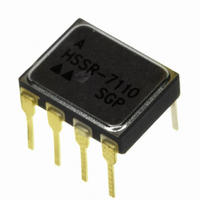
ISOLAT 1.5KVDC 1CH GATE DVR 8DIP

HSSR-7110

Manufacturer Part Number
HSSR-7110
Description
ISOLAT 1.5KVDC 1CH GATE DVR 8DIP
Manufacturer
Avago Technologies US Inc.
Type
Analogr
Datasheets

Specifications of HSSR-7110

Mounting Type
Through Hole
Voltage - Isolation
1500VDC
Number Of Channels
1, Unidirectional
Current - Output / Channel
1.6A
Current - Dc Forward (if)
20mA
Input Type
DC
Output Type
Gate Driver
Package / Case
8-DIP (0.300", 7.62mm)
No. Of Channels
1
Optocoupler Output Type
Gate Drive
Input Current
20mA
Output Voltage
90V
Opto Case Style
DIP
No. Of Pins
8
Isolation Voltage
1.5kV
Package
8CDIP
Circuit Arrangement
1 Form A
Output Device
MOSFET
I/o Isolation Voltage
1500 V
Maximum Input Current
20 mA
Maximum Output Current
0.8 A
Maximum Input Voltage
1.7 V
Maximum Output Voltage
90 V
Load Voltage Rating
90 V
Load Current Rating
0.8 A
Contact Form
1 Form A
Maximum Operating Temperature
+ 125 C
Minimum Operating Temperature
- 55 C
Package Type
8-Pin DIP
Power Dissipation
800 mW (Max.) Output
Special Features
Hermetic
Temperature, Storage
125 °C
Input Voltage (max)
1.7V
Output Voltage (max)
90V
Input Current (max)
20mA
Output Current
800mA
Pin Count
8
Mounting
Through Hole
Operating Temp Range
-55C to 125C
Operating Temperature Classification
Military
Rad Hardened
No
Input Current Max
20mA
Rohs Compliant
Yes
Lead Free Status / RoHS Status
Lead free by exemption / RoHS compliant by exemption
Lead Free Status / RoHS Status
Lead free / RoHS Compliant, Lead free by exemption / RoHS compliant by exemption
Other names
516-1943-5
HSSR-7110

Available stocks

Company
Part Number
Manufacturer
Quantity
Price
Part Number:
HSSR-7110
Quantity:
650
Part Number:
HSSR-7110
Manufacturer:
LATTICE
Quantity:
650
Part Number:
HSSR-7110#300
Manufacturer:
ON
Quantity:
12 000
Part Number:
HSSR-7110#300
Manufacturer:
XICOR
Quantity:
780
Part Number:
HSSR-7110SGP
Manufacturer:
HP/A
Quantity:
19
Description
The HSSR-7110, HSSR-7111,
HSSR-7112, HSSR-711E and
SMD 5962-93140 are single
channel power MOSFET
optocouplers, constructed in
eight-pin, hermetic, dual-in-
line, ceramic packages. The
devices operate exactly like a
solid-state relay.
The products are capable of
operation and storage over the
full military temperature range
and may be purchased as a
standard product (HSSR-7110),
with full MIL-PRF-38534 Class
H testing (HSSR-7111 and
HSSR- 7112), with MIL-PRF-
38534 Class E testing (Class K
Functional Diagrams
V
I
F
CAUTION: It is advised that normal static precautions be taken in handling and assembly of
this component to prevent damage and/or degradation which may be induced by ESD.
F
+
-
1
2
3
4
AC/DC CONNECTION
NC
NC
CONNECTION A
8
7
6
5
V
I
O
+
O
-
V
I
F
F
+
-
1
2
3
4
NC
NC
DC CONNECTION
CONNECTION B
Agilent HSSR-7110, HSSR-7111 &
HSSR-7112, HSSR-711E
5962-9314001, 5962-9314002
90 V/1.0 Ω Ω Ω Ω Ω , Hermetically Sealed,
Power MOSFET Optocoupler
Technical Data
with exceptions) (HSSR-711E)
or from the DSCC Standard
Microcircuit Drawing (SMD)
5962-93140. Details of the
Class E program may be found
on page 11 of this datasheet.
Applications
• • • • • Military and Space
• • • • • High Reliability Systems
• • • • • Standard 28 Vdc and 48 Vdc Load
• • • • • Standard 24 Vac Load Driver
• • • • • Aircraft Controls
• • • • • ac/dc Electromechanical and
• • • • • I/O Modules
• • • • • Harsh Industrial Environments
Driver
Solid State Relay Replacement
8
7
6
5
I
V
O
+
O
-
TRUTH TABLE
INPUT
H
L
OUTPUT
CLOSED
OPEN
Features
• • • • • Dual Marked with Device Part
• • • • • ac/dc Signal & Power Switching
• • • • • Compact Solid-State Bidirectional
• • • • • Manufactured and Tested on a
• • • • • QML-38534
• • • • • MIL-PRF-38534 Class H
• • • • • Modified Space Level Processing
• • • • • Hermetically Sealed 8-Pin Dual
• • • • • Small Size and Weight
• • • • • Performance Guaranteed over
• • • • • Connection A 0.8 A, 1.0 Ω Ω Ω Ω Ω
• • • • • Connection B 1.6 A, 0.25 Ω Ω Ω Ω Ω
• • • • • 1500 Vdc Withstand Test Voltage
• • • • • High Transient Immunity
• • • • • 5 Amp Output Surge Current
Number and DSCC Standard
Microcircuit Drawing
Switch
MIL-PRF-38534 Certified Line
Available (Class E)
In-Line Package
-55°C to +125°C

Related parts for HSSR-7110

HSSR-7110 Summary of contents

Page 1

... NC 5 CAUTION advised that normal static precautions be taken in handling and assembly of this component to prevent damage and/or degradation which may be induced by ESD. Agilent HSSR-7110, HSSR-7111 & HSSR-7112, HSSR-711E 5962-9314001, 5962-9314002 90 V/1.0 Ω Ω Ω Ω Ω , Hermetically Sealed, Power MOSFET Optocoupler Technical Data ...

Page 2

... Selection Guide table for details. Standard Microcircuit Drawing (SMD) parts are available for each package and lead style. The HSSR-7110, HSSR-7111, HSSR-7112, HSSR-711E and SMD 5962-93140 are designed to switch loads on 28 Vdc power systems. They meet 80 V surge and ± 600 V spike requirements ...

Page 3

Outline Drawing 8-pin DIP Through Hole 9.40 (0.370) 9.91 (0.390) 0.76 (0.030) 1.27 (0.050) 4.32 (0.170) MAX. 0.51 (0.020) 3.81 (0.150) MIN. MIN. 2.29 (0.090) 0.51 (0.020) 2.79 (0.110) MAX. NOTE: DIMENSIONS IN MILLIMETERS (INCHES). Absolute Maximum Ratings Parameter Storage ...

Page 4

Recommended Operating Conditions Parameter Input Current (on) Input Current (on) Input Voltage (off) Operating Temperature Hermetic Optocoupler Options Note: Dimensions in millimeters (inches). Option Description 100 Surface mountable hermetic optocoupler with leads trimmed for butt joint assembly. This option is ...

Page 5

Electrical Specifications T =-55°C to +125°C, unless otherwise specified. See note 9. A Sym. Group A, Parameter Sub-group Output Withstand |V | O(OFF) Voltage Output On-Resistance Connection A R (ON) Connection B Output Leakage I O(OFF) Current Input Forward V ...

Page 6

... Standard parts receive 100% testing at 25°C (Subgroups 1 and 9). SMD, Class H and Class E parts receive 100% testing at 25°C, 125°C and -55°C (Subgroups 1 and 9, 2 and 10, 3 and 11 respectively). 10. Applies to HSSR-7112 and 5962-9314002Hxx devices only. 11. Applies to HSSR-7110, HSSR-7111, HSSR-711E, 5962-9314001Hxx and 5962-9314001Exx devices only. V (+5V) ...

Page 7

CONNECTION - 0.2 = 40˚ C 80˚ C -55 - 125 155 T - AMBIENT TEMPERATURE - ˚C A Figure 2. Maximum Average ...

Page 8

... CONNECTION 800 mA O 14.4 14.2 14.0 13.8 13.6 13.4 13.2 -55 - 125 T -TEMPERATURE - ˚C A Figure 14. Typical Turn Off Time vs. Temperature. 8 PULSE GEN HSSR-7110 MONITOR R (MONITOR) 200 . GND 3.0 CONNECTION 2 800 25˚C A 2.2 1.8 1.4 1.0 0.6 0 INPUT CURRENT - mA F Figure 12. Typical Turn On Time vs. Input Current ...

Page 9

... INCLUDES PROBE AND FIXTURE CAPACITANCE M R INCLUDES PROBE AND FIXTURE RESISTANCE M 90% 10 (0.8) V (PEAK 10 90% 10 (min) 3.25 V O(OFF) V (max) 0.8 O(ON mA) F (0.8) V I-O(PEAK) I-O(PEAK 10% I-O(PEAK) HSSR-7110 PEAK + - 5 PULSE GENERATOR V DD HSSR-7110 INCLUDES PROBE PLUS ( FIXTURE CAPACITANCE ) I PULSE GENERATOR V M MONITOR NODE ...

Page 10

... CORRECT OUTPUT CURRENT PER FIGURES 2 AND 4 TO INSURE THAT THE DEVICE MEETS THE DERATING REQUIREMENTS AS SHOWN. Figure 20. Burn-In Circuit. Applications Information Thermal Model The steady state thermal model for the HSSR-7110 is shown in Figure 21. The thermal resistance values given in this model can be used to calculate the temperatures at each node for a given operating condition ...

Page 11

... The drive circuit should maintain at least LED current during the ON condition. If the LED forward current is less than the 5 mA level, it will cause the HSSR-7110 to turn on with a longer delay. In addition, the power dissipation in the output power MOSFETs increases, which, in turn, may 11 ...

Page 12

For product information and a complete list of distributors, please go to our web site. For technical assistance call: Americas/Canada: +1 (800) 235-0312 or (408) 654-8675 Europe: +49 (0) 6441 92460 China: 10800 650 0017 Hong Kong: (+65) ...

Related keywords