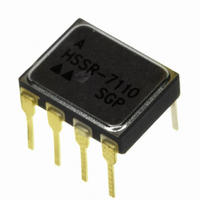
HSSR-7110 Avago Technologies US Inc., HSSR-7110 Datasheet - Page 7

HSSR-7110
Manufacturer Part Number
HSSR-7110
Description
ISOLAT 1.5KVDC 1CH GATE DVR 8DIP
Manufacturer
Avago Technologies US Inc.
Type
Analogr
Specifications of HSSR-7110
Mounting Type
Through Hole
Voltage - Isolation
1500VDC
Number Of Channels
1, Unidirectional
Current - Output / Channel
1.6A
Current - Dc Forward (if)
20mA
Input Type
DC
Output Type
Gate Driver
Package / Case
8-DIP (0.300", 7.62mm)
No. Of Channels
1
Optocoupler Output Type
Gate Drive
Input Current
20mA
Output Voltage
90V
Opto Case Style
DIP
No. Of Pins
8
Isolation Voltage
1.5kV
Package
8CDIP
Circuit Arrangement
1 Form A
Output Device
MOSFET
I/o Isolation Voltage
1500 V
Maximum Input Current
20 mA
Maximum Output Current
0.8 A
Maximum Input Voltage
1.7 V
Maximum Output Voltage
90 V
Load Voltage Rating
90 V
Load Current Rating
0.8 A
Contact Form
1 Form A
Maximum Operating Temperature
+ 125 C
Minimum Operating Temperature
- 55 C
Package Type
8-Pin DIP
Power Dissipation
800 mW (Max.) Output
Special Features
Hermetic
Temperature, Storage
125 °C
Input Voltage (max)
1.7V
Output Voltage (max)
90V
Input Current (max)
20mA
Output Current
800mA
Pin Count
8
Mounting
Through Hole
Operating Temp Range
-55C to 125C
Operating Temperature Classification
Military
Rad Hardened
No
Input Current Max
20mA
Rohs Compliant
Yes
Lead Free Status / RoHS Status
Lead free by exemption / RoHS compliant by exemption
Lead Free Status / RoHS Status
Lead free / RoHS Compliant, Lead free by exemption / RoHS compliant by exemption
Other names
516-1943-5
HSSR-7110
HSSR-7110
Available stocks
Company
Part Number
Manufacturer
Quantity
Price
Company:
Part Number:
HSSR-7110#300
Manufacturer:
ON
Quantity:
12 000
Company:
Part Number:
HSSR-7110SGP
Manufacturer:
HP/A
Quantity:
19
Figure 2. Maximum Average Output Current Rat-
ing vs. Ambient Temperature.
Figure 5. Normalized Typical Output Withstand
Voltage vs. Temperature.
Figure 8. Typical Output Leakage Current vs.
Temperature.
7
10
10
1.0
0.8
0.6
0.4
0.2
10
10
10
-10
-11
0
-55
1.10
1.08
1.06
1.04
1.02
1.00
0.98
0.96
0.94
0.92
-7
-8
-9
20
CONNECTION - A
I
F
-55
T
CONNECTION A
V
V
-25
A
F
O
10 mA
V
I
O
35
θ
θ
- AMBIENT TEMPERATURE - ˚C
F
= 0.6 V
= 90 V
CA
CA
= 10 µA
= 0.6 V
T
-25
T
A
5
A
= 40˚ C/W
= 80˚ C/W
- AMBIENT TEMPERATURE - ˚C
- TEMPERATURE - ˚C
35
5
65
65
35
95
95
65
125
95
155
125
125
Figure 6. Normalized Typical Output Resistance
vs. Temperature.
Figure 3. Single Shot (non-repetitive) Output
Current vs. Pulse Duration.
Figure 9. Typical Input Forward Current vs. Input
Forward Voltage.
10
10
10
10
10
10
12
11
10
9
8
7
6
5
4
3
1.8
1.6
1.4
1.2
1.0
0.8
0.6
-1
-2
-3
-4
-5
-6
10
0.4
-55
T
CONNECTION - A
I
I
(PULSE DURATION 30 ms)
A
F
O
V
= 125˚C
= 800 mA
200
0.6
F
T
10 mA
-25
A
- INPUT FORWARD VOLTAGE - V
PULSE DURATION - ms
- AMBIENT TEMPERATURE - ˚C
0.8
CONNECTION-B
CONNECTION-A
400
5
1.0
35
600
I
1.2
F
65
T
T
10 mA
800
A
A
= 25˚C
= -55˚C
1.4
95
1000
125
1.6
Figure 4. Output Power Rating vs. Ambient
Temperature.
Figure 7. Typical On State Output I-V Character-
istics.
1.0
0.8
0.6
0.4
0.2
-0.2
-0.4
-0.6
-0.8
0.8
0.6
0.4
0.2
0
-55
0
-0.6
CONNECTION - A
I
I
O
O
CONNECTION - A
I
F
T
-25
(PULSE DURATION
A
-0.4
10 mA
10 mA
30 ms)
- AMBIENT TEMPERATURE - ˚C
θ
θ
V
CA
CA
O
5
- OUTPUT VOLTAGE - V
= 80˚ C/W
= 40˚ C/W
-0.2
35
0
65
T
T
T
A
A
A
= 125˚C
= 25˚C
= -55˚C
0.2
95
125
0.4
155
0.6


