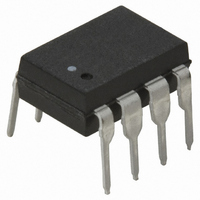
HCPL-4200 Avago Technologies US Inc., HCPL-4200 Datasheet - Page 12

HCPL-4200
Manufacturer Part Number
HCPL-4200
Description
OPTOCOUPLER RECEIVER 20MA 8-DIP
Manufacturer
Avago Technologies US Inc.
Type
Receiverr
Specifications of HCPL-4200
Mounting Type
Through Hole
Voltage - Isolation
3750Vrms
Input Type
DC
Voltage - Supply
4.5 V ~ 20 V
Operating Temperature
0°C ~ 70°C
Package / Case
8-DIP (0.300", 7.62mm)
No. Of Channels
1
Isolation Voltage
3.75kV
Optocoupler Output Type
Logic Gate
Input Current
24mA
Output Voltage
20V
Opto Case Style
DIP
No. Of Pins
8
Propagation Delay
0.23µs
Output Type
And
Package Type
8-Pin DIP
Lead Free Status / RoHS Status
Contains lead / RoHS non-compliant
Other names
516-1149-5
Available stocks
Company
Part Number
Manufacturer
Quantity
Price
Company:
Part Number:
HCPL-4200
Manufacturer:
AVAGO
Quantity:
5 000
Part Number:
HCPL-4200
Manufacturer:
AVAGO/安华高
Quantity:
20 000
Company:
Part Number:
HCPL-4200#300
Manufacturer:
AVAGO
Quantity:
7 000
Company:
Part Number:
HCPL-4200#500
Manufacturer:
AVAGO
Quantity:
7 000
Company:
Part Number:
HCPL-4200-000E
Manufacturer:
AVAGO
Quantity:
5 000
Part Number:
HCPL-4200-000E
Manufacturer:
AVAGO/安华高
Quantity:
20 000
Company:
Part Number:
HCPL-4200-300E
Manufacturer:
AVAGO
Quantity:
5 000
Part Number:
HCPL-4200-300E
Manufacturer:
AVAGO/安华高
Quantity:
20 000
Part Number:
HCPL-4200-500E
Manufacturer:
AVAGO/安华高
Quantity:
20 000
Figure 18. Recommended Non-Isolated Active Transmitter with HCPL-4200 Isolated Receiver for Simplex Point-to-Point 20 mA Current Loop.
Full Duplex
The full duplex point-to-point communication of Figure
21 uses a four wire system to provide simultaneous, bi-
directional data communication between local and re-
mote equipment. The basic application uses two simplex
point-to-point loops which have two separate, active,
non-isolated units at one common end of the loops. The
other end of each loop is isolated.
As Figure 21 illustrates, the combination of Avago current
loop optocouplers, HCPL-4100 transmitter and HCPL-
4200 receiver, can be used at the isolated end of current
loops. Cross talk and common mode coupling are greatly
reduced when optical isolation is imple mented at the
same end of both loops, as shown. The full duplex data
rate is limited by the non-isolated active receiver current
loop. Comments mentioned under simplex configura-
tion apply to the full duplex case. Consult the HCPL-4100
transmitter opto coupler data sheet for specified device
performance.
Figure 19. Minimum Required Supply Voltage, V
Loop Length for Current Loop Circuit of Figure 19.
12
CC
, vs.
Half Duplex
The half duplex configuration, whether point-to-point
or multidrop, gives non-simultaneous bidirectional data
flow from transmitters to receivers shown in Figures 22a
and 22b. This configuration allows the use of two wires
to carry data back and forth between local and remote
units. However, protocol must be used to determine
which specific transmitter can operate at any given time.
Maximum data rate for a half duplex system is limited
by the loop current charging time. These considerations
were explained in the Simplex config ura tion section.
Figures 22a and 22b illustrate half duplex application
for the combination of HCPL-4100/-4200 optocouplers.
The unique and complementary designs of the HCPL-
4100 transmitter and HCPL-4200 receiver optocouplers
provide many designed-in benefits. For example, total
optical isolation at one end of the current loop is eas-
ily accomplished, which results in substantial removal
Figure 20. Typical Data Rate vs. Distance.


