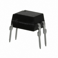
TCET1105 Vishay, TCET1105 Datasheet

TCET1105
Specifications of TCET1105
TCET1105GI
TCET1105VS
Available stocks
Related parts for TCET1105
TCET1105 Summary of contents
Page 1
... TCET1100, TCET1100G Vishay Semiconductors Optocoupler, Phototransistor Output, High Temperature C 17197_5 17197_4 DESCRIPTION The TCET110. consists of a phototransistor optically coupled to a gallium arsenide infrared-emitting diode in a 4-lead plastic dual inline package. AGENCY APPROVALS • UL1577, file no. E52744, double protection • cUL tested, file A52744 • ...
Page 2
... TCET1101 TCET1102 TCET1103 TCET1104 TCET1105 TCET1106 TCET1107 TCET1108 TCET1109 TCET1100G TCET1101G TCET1102G TCET1103G TCET1104G TCET1105G TCET1106G TCET1107G TCET1108G TCET1109G Note G = lead form 10.16 mm not marked on the body ABSOLUTE MAXIMUM RATINGS PARAMETER INPUT Reverse voltage Forward current Forward surge current OUTPUT Collector emitter voltage ...
Page 3
... The thermal model is represented in the thermal network below. Each resistance value given in this model can be used to calculate the temperatures at each node for a given operating condition. The thermal resistance from board to ambient will be dependent on the type of PCB, layout and thickness of copper traces. For a detailed explanation of the thermal model, please reference Vishay’s “Thermal Characteristics of Optocouplers” application note. ...
Page 4
... For technical questions, contact: Rev. 2.3, 14-Oct-09 Optocoupler, Phototransistor Output, High Temperature PART SYMBOL TCET1101 TCET1101G TCET1102 TCET1102G = TCET1103 TCET1103G TCET1104 TCET1104G TCET1100 TCET1100G TCET1105 TCET1105G TCET1106 TCET1106G = TCET1107 TCET1107G TCET1108 TCET1108G TCET1109 TCET1109G TCET1101 TCET1101G TCET1102 TCET1102G = TCET1103 TCET1103G TCET1104 ...
Page 5
... TCET1100, TCET1100G Vishay Semiconductors 300 Phototransistor 250 P (mW) si 200 150 100 IR-diode 50 I (mA 100 T - Safety Temperature (°C) 94 9182 si Fig Derating Diagram SWITCHING CHARACTERISTICS PARAMETER Delay time Rise time Turn-on time Storage time Fall time Turn-off time Turn-on time Turn-off time + Ω ...
Page 6
... Optocoupler, Phototransistor Output, High Temperature off Storage time Fall time + t ) Turn-off time f 96 11698 120 1.6 2.0 95 11026 Fig Collector Dark Current vs. Ambient Temperature optocoupleranswers@vishay.com TCET1100, TCET1100G Vishay Semiconductors 2 1.5 1.0 0 Ambient Temperature (°C) 95 11025 amb Fig Relative Current Transfer Ratio vs. ...
Page 7
... TCET1100, TCET1100G Vishay Semiconductors 100 0.1 0.01 0 Forward Current (mA) 95 11027 F Fig Collector Current vs. Forward Current 100 0.1 0 Collector Emitter Voltage (V) 95 10985 CE Fig Collector Current vs. Collector Emitter Voltage 1 used 0.8 CTR = 50 % used 0.6 0.4 0 used Collector Current (mA) 95 11028 C Fig Collector Emitter Saturation Voltage vs. ...
Page 8
... TCET1100G type 7.62 typ. 4.5 ± 0.3 2.55 ± 0.25 10.16 typ. 20802-3 ET1100 V YWW 24 21764-3 optocoupleranswers@vishay.com TCET1100, TCET1100G Vishay Semiconductors 7.62 to 9.5 7.62 typ. 2.8 ± 0.5 0° to 15° 0.25 typ. www.vishay.com 817 ...
Page 9
... Vishay disclaims any and all liability arising out of the use or application of any product described herein or of any information provided herein to the maximum extent permitted by law. The product specifications do not expand or otherwise modify Vishay’ ...


