PC827 Sharp Microelectronics, PC827 Datasheet

PHOTOCOUPLER 2CH TRAN OUT 8-DIP

PC827

Manufacturer Part Number
PC827
Description
PHOTOCOUPLER 2CH TRAN OUT 8-DIP
Manufacturer
Sharp Microelectronics
Datasheet

Specifications of PC827

Rohs Status
RoHS non-compliant
Number Of Channels
2
Input Type
DC
Voltage - Isolation
5000Vrms
Current Transfer Ratio (min)
50% @ 5mA
Voltage - Output
35V
Current - Output / Channel
50mA
Current - Dc Forward (if)
50mA
Vce Saturation (max)
200mV
Output Type
Transistor
Mounting Type
Through Hole
Package / Case
8-DIP
Current Transfer Ratio (max)
-
Other names
425-1481-5

Available stocks

Company
Part Number
Manufacturer
Quantity
Price
Part Number:
PC827
Manufacturer:
SHARP
Quantity:
5 170
Part Number:
PC827
Manufacturer:
SHARP
Quantity:
20 000
PC817 Series
1. Current transfer ratio
2. High isolation voltage between input and
3. Compact dual-in-line package
4. Recognized by UL, file No. E64380
“ In the absence of confirmation by device specification sheets, SHARP takes no responsibility for any defects that occur in equipment using any of SHARP's devices, shown in catalogs,
data books, etc. Contact SHARP in order to obtain the latest version of the device specification sheets before using any SHARP's device.”
PC817
PC837
Anode mark
( CTR: MIN. 50% at I
output ( V
Features
Outline Dimensions
CTR
rank mark
Lead forming type ( I type ) and taping reel type ( P type ) are also available. ( PC817I/PC817P )
PC817 : 1-channel type
PC827 : 2-channel type
PC837 : 3-channel type
PC847 : 4-channel type
TUV ( VDE0884 ) approved type is also available as an option.
..
12
1
11
2.54
1
0.9
1.2
0.5
2
4
4.58
iso
14.74
2.54
± 0.2
± 0.3
10
± 0.1
± 0.25
3 4
: 5 000V
0.9
1.2
0.5
2
± 0.5
9
± 0.25
3
± 0.5
± 0.2
± 0.3
± 0.1
8
5 6
7
rms
F
Internal connection diagram
= 5mA ,V
)
= 0 to 13 ˚
7.62
0.26
diagram
Internal connection
12
4
1 2
1 2
± 0.3
± 0.1
11
3
CE
1 3 5 Anode
2 4 6 Cathode
7 9
8
= 0 to 13 ˚
7.62
0.26
10
=5V)
10
3 4
11
12
± 0.3
9
± 0.1
Emitter
Collector
1 Anode
2 Cathode
4 Collector
3 Emitter
8
5 6
7
Anode
mark
PC827
PC847
High Density Mounting Type
Photocoupler
1. Computer terminals
2. System appliances, measuring instruments
3. Registers, copiers, automatic vending
4. Electric home appliances, such as fan
5. Signal transmission between circuits of
16
1
machines
1
different potentials and impedances
Applications
heaters, etc.
8
15
0.9
1.2
2
7
9.66
2
± 0.2
± 0.3
0.9 ± 0.2
1.2 ± 0.3
0.5
2.54
14
3 4
0.5
2.54
± 0.1
± 0.5
6
3
± 0.25
13
± 0.1
± 0.25
19.82
5
4
12
5 6
1 3 5 7 Anode
2 4 6 8 Cathode
11
± 0.5
10
7 8
Internal connection diagram
9
8
1 2
7.62
0.26
= 0 to 13 ˚
7
16
1
diagram
Internal connection
± 0.3
± 0.1
6
3 4
15
2
10
9
5
14
3 4
12
11
= 0 to 13 ˚
PC817 Series
14
13
7.62
13
0.26
16
15
( Unit : mm )
1 3 Anode
2 4 Cathode
5 7 Emitter
6 8 Collector
12
5 6
± 0.3
± 0.1
Emitter
Collector
11
10
7 8
9

Related parts for PC827

PC827 Summary of contents

Page 1

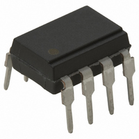
... CTR: MIN. 50 5mA , High isolation voltage between input and output ( 000V iso rms 3. Compact dual-in-line package PC817 : 1-channel type PC827 : 2-channel type PC837 : 3-channel type PC847 : 4-channel type 4. Recognized by UL, file No. E64380 Outline Dimensions PC817 Internal connection diagram ± 0.25 2. CTR ...

Page 2

Absolute Maximum Ratings Parameter Forward current *1 Peak forward current Input Reverse voltage Power dissipation Collector-emitter voltage Emitter-collector voltage Output Collector current Collector power dissipation Total power dissipation *2 Isolation voltage Operating temperature Storage temperature *3 Soldering temperature *1 Pulse ...

Page 3

Fig. 2 Collector Power Dissipation vs. Ambient Temperature 200 150 100 Ambient temperature T Fig. 4 Current Transfer Ratio vs. Forward Current 200 180 160 140 120 100 ...

Page 4

Fig. 8 Collector-emitter Saturation Voltage vs. Ambient Temperature 0.16 0.14 0.12 0.10 0.08 0.06 0.04 0. Ambient temperature T Fig.10 Response Time vs. Load Resistance 500 200 I = 2mA ...

Page 5

Application Circuits NOTICE The circuit application examples in this publication are provided to explain representative applications of SHARP devices and are not intended to guarantee any circuit design or license any intellectual property rights. SHARP takes no responsibility for any ...

Related keywords