LQ038Q7DB03R Sharp Microelectronics, LQ038Q7DB03R Datasheet
LQ038Q7DB03R
Specifications of LQ038Q7DB03R
Available stocks


Related parts for LQ038Q7DB03R


LQ038Q7DB03R Summary of contents
Page 1
... P S RODUCT PECIFICATIONS LQ038Q7DB03R TFT-LCD Module Spec. Issue Date: May 20, 2005 No: LCP-05007 Mobile Liquid Crystal Displays Group ...
Page 2
...
Page 3
RECORDS OF REVISION MODEL No:LQ038Q7DB03R SPEC No :LCP−05007 NO. 2005.05.18 LCP-5007 PAGE SUMMARY - - NOTE 1 st Issue ...
Page 4
This publication is the proprietary of SHARP and is copyrighted, with all rights reserved. Under the copyright laws, no part of this publication may be reproduced or transmitted in any form or by any means, electronic or mechanical for any ...
Page 5
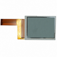
... Application This literature applies to LQ038Q7DB03R. (2) Overview This module is a color reflective and active matrix LCD module incorporating amorphous silicon TFT (Thin Film Transistor), named AD-TFT(Advanced TFT composed of a color TFT-LCD panel, driver ICs, an FPC, a back light, and a back sealed casing. It isn’t composed control circuit. Graphics and texts can be displayed on a 240× ...
Page 6
Table2 Pin No. Symbol I/O DGND Ground(digital) − Power supply(analog) − 2 SHA NC − − Power supply of digital SHD 5 V Power supply of gate driver(high level) ...
Page 7
Pin No. Symbol I − − 40 AGND Ground(Analog) − − − − 44 DCLK I Data sampling clock signal 45 SPL I/O Sampling start signal Data ...
Page 8
Maximum Ratings Table 4 Parameter Power supply(source/Analog) Power supply(source/Digital) Power supply (gate) Power supply (gate) Power supply (gate) Power supply (gate) Input voltage (Analog) Input voltage (Digital) Operating temperature (panel surface) Storage temperature [Terminal①] V0,V1,V2,V3,V4 [Terminal②] MOD,U/L,SPS,CLS,SPL,R0∼R5,G0∼G5,B0∼B5,LP,DCLK,LBR,SPR,PS 【Note6-1】Humidity: 95%RH ...
Page 9
Cautions when you turn on or off the power supply ① Turn on or off the power supply with simultaneously or the following sequence. Turn on … V →V SHD Turn off … V → ② The ...
Page 10
Timing Characteristics of input signals Table 8 AC Characteristics (1) Parameter Clock frequency of source driver Rising time of clock Falling time of clock Pulse width (High level) Pulse width (Low level) Frequency of start pulse Setup time of ...
Page 11
DCLK 20% T wlp LP T susp T sulp SPL T wsp R0∼R5 G0∼G5 B0∼B5 T hcls CLS T sups PS V COM 80% 80 20% T cwl T cwh T hsp T ...
Page 12
T fcls T rcls T whcls T wlcls 80% 80% CLS 1 2 20% 20% 20% T susps T hsps 80% 80% SPS 20% 20% T fsps T rsps R0∼R5 G0∼G5 Non-display period B0∼B5 T fcls 8 9 20% ...
Page 13
Measurement condition : SPS=60Hz,CLS=15.73kHz,SPL=15.73kHz,DCLK=6.3MHz The term of PS=”Lo” in one horizontal period … 37μsec(234DCLK) Ta=25℃ Table 9 Parameter Sym Source Analog I SHA current Digital I SHD Gate High I DD current Low I EE logic High I ...
Page 14
Signals, Basic Display Color and Gray Scale of Each Colornn Table 10 Colors & Gray scale Gray Scale Black − Blue − Green − Cyan 0 0 ...
Page 15
Back light condition Table 12 Parameter Symbol θ21,22 Viewing angle θ11 Range θ12 Contrast ratio CRmax τ r Response Rise τ d Time Fall White - x White - y Red - x Red - ...
Page 16
Measuring method (b) for optical characteristics Photodetector (with luminosity correction system) light source 30° Module LCP-05007−13 ...
Page 17
Back light condition Table 13 Parameter Symbol θ21,22 Viewing angle θ11 range θ12 Contrast ratio Crmax τ r Response Rise τ d time Fall White - x White - y Red - x Red - y Color chromaticity ...
Page 18
Viewing angle range is defined as follows. θ 22 θ 11 6o’clock direction Definition for viewing angle [Note 9-2] Definition of contrast ratio: The contrast ratio is defined as follows: Photodetecter output with all pixels white(GS63) Contrast ratio(CR)= ...
Page 19
A measurement device is Minolta CM-2002. [Note 9-6] Definition of reflection ratio Reflection ratio = [Note 9-7] The White-LED life time is defined as a time when brightness not to become under 50% of the original value.(at Ta=25℃) ...
Page 20
Precautions 12-1) Insertion and taking out of FPCs Be sure insert and take out of the FPC into the connector of the set after turning off the power supply on the set side. 12-2) Handling of FPCs The FPC ...
Page 21
... Others 14-1)Indication of lot number The lot number is shown on a label. Attached location is shown in Fig.1 (Outline Dimensions). Indicated contents of the label LQ038Q7DB03R model No. 14-2) Used Regulation of Chemical Substances Breaking Ozone Stratum Substances with the object of regulating : CFCS, Carbon tetrachloride, Halon (a) This LCD module, Constructed part and Parts don’t contain the above substances. ...
Page 22
...
Page 23
... LCP-05007−20 LQ038Q7DB03R ...
Page 24
... ALL EXPRESS AND IMPLIED WARRANTIES, INCLUDING THE WARRANTIES OF MERCHANTABILITY, FITNESS FOR USE AND FITNESS FOR A PARTICULAR PURPOSE, ARE SPECIFICALLY EXCLUDED event will SHARP be liable any way responsible, for any incidental or consequential economic or property damage. NORTH AMERICA SHARP Microelectronics of the Americas 5700 NW Pacific Rim Blvd. Camas, WA 98607, U.S.A. Phone: (1) 360-834-2500 ...