F-51373GNC-LW-AUN Optrex America Inc, F-51373GNC-LW-AUN Datasheet
F-51373GNC-LW-AUN
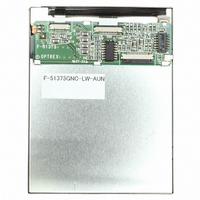
Specifications of F-51373GNC-LW-AUN
Available stocks


Related parts for F-51373GNC-LW-AUN


F-51373GNC-LW-AUN Summary of contents
Page 1
... Test ................................................................................................................................................................... 13 6. Appearance Standards 7. Code System of Production Lot 8. Type Number .................................................................................................................................................. 17 9. Applying Precautions .................................................................................................................................. 17 10. Precautions Relating Product Handling 11. Warranty ........................................................................................................................................................ 19 Revision History Rev. Date F-51373GNC-LW-AUN (AU) No. 2005-0081 .................................................................................................................................. 2 ............................................................................................................................... 3 ................................................................................................................................... 9 ................................................................................................................................ 14 ............................................................................................................... 17 ................................................................................................ 18 Page Comment OPTREX CORPORATION First Edition Aug 1, 2005 Final Revision ****** Approved by (Quality Assurance Division) ...
Page 2
... Data Transfer : Backlight : Drawings : RoHS regulation : F-51373GNC-LW-AUN (AU) No. 2005-0081 min ~max min. -20 C ~max 240 × 3 [R.G.B] (W) × 320 (H) dots 0.070 (W) × 0.225 (H) mm 0.24 (W) × 0.24 (H) mm 59.0 (W) × 80.3 (H) mm 73.0 (W) × 94.4 (H) × 7.3max. (D) mm 57.6g max. ...
Page 3
... Drive) High Level V IH Input Voltage High Level V OH output Voltage Low Level V IL Input Voltage Low Level V OL output Voltage I CC Supply Current I LCD F-51373GNC-LW-AUN (AU) No. 2005-0081 Conditions Min. - -0.3 - -0.3 - -0.3 Conditions Min. - 2.7 Shown in 3.1 V =2.7~5.5V 0 =-0.4mA V ...
Page 4
... Latch Pulse Fall to Shift Clock Rise Time Input Signal Rise,Fall Time DISPOFF Removal Time DISPOFF Enable Pulse Width Output Delay Time t Note twckll - twckl)/2 is the maximum in case of high speed operation. CK – Note =15Pf L F-51373GNC-LW-AUN (AU) No. 2005-0081 Symbol Min. Max WCK WCKH ...
Page 5
... Latch Pulse Fall to Shift Clock Rise Time Input Signal Rise,Fall Time DISPOFF Removal Time DISPOFF Enable Pulse Width Output Delay Time t Note twckll - twckl)/2 is the maximum in case of high speed operation. CK – Note =15pF L FLM D0~D7 DISPOFF F-51373GNC-LW-AUN (AU) No. 2005-0081 Symbol Min WCK t 28 WCKH t 28 WCKL ...
Page 6
... SEG SEG 705~ 713 712 720 8 FLM LP (Reduction) FLM (Reduction) 2.4. Comparison of Display and Data SEG1 # TOP VIEW #320 F-51373GNC-LW-AUN (AU) No. 2005-0081 T=0.04464ms typ. SEG #1 DATA 9~ 16 320 xT SEG720 D0 D0~D7 OPTREX CORPORATION SEG SEG SEG SEG 705~ 713 712 720 8 16 ...
Page 7
... VSS VLCD VSS VCC VSS Please maintain the above sequence when turning on and off the power supply of the module. If DISPOFF is supplied to the module unstable, DC component will be supplied to the LCD panel. This may cause damage the LCD module. F-51373GNC-LW-AUN (AU) No. 2005-0081 hile internal alternate signal for LCD driving (M) is ...
Page 8
... Foward Voltage V LED Power Dissipation P Note defined as the voltage between ANODE and CATHODE as shown below. F LED+ LED- 2.6.2. Operating Characteristics (Only LED) Parameter Symbol Foward Current Luminance of Backlight Surface Parameter Symbol Luminance of Module F-51373GNC-LW-AUN (AU) No. 2005-0081 Conditions Min. Note Conditions Min 10. ...
Page 9
... Assuming that the typical driving waveforms shown below are applied to the LCD Panel at 1/A Duty - 1/B Bias (A: Duty Number, B: Bias Number). Driving voltage V is definded as the voltage V OD maximum <ON SIGNAL> F-51373GNC-LW-AUN (AU) No. 2005-0081 Conditions Ta Ta= Ta=50 C Ta=25 C, 1/320 Duty, 1/15 Bias, V Conditions =270 T - ...
Page 10
... Duty, 1/15 Bias 135 180 225 270 shows typ (Measuring Spot : 3.0mm ) *Area 3.4. System Block Diagram Photometer #1980A WB Computer F-51373GNC-LW-AUN (AU) No. 2005-0081 f =24.2V, =70Hz 180 315 270 Temperature Chamber Rotation Table ( , ) Control Unit & ...
Page 11
... D0 Display Data 16 V Power Supply (0V, GND Power Supply for LCD Drive LCD 18 LED+ LED Anode Terminal 19 LED+ LED Anode Terminal 20 LED- LED Cathode Terminal 21 LED- LED Cathode Terminal 22 V Power Supply (0V, GND) SS F-51373GNC-LW-AUN (AU) No. 2005-0081 Function OPTREX CORPORATION Page 11/19 ...
Page 12
... It is recommended to apply a potentiometer for the contrast adjust due to the tolerance of the driving voltage and its temperature dependence. MODULE 4.3. Block Diagram FLM LP DISPOFF CP D0~D 7 VLCD VCC VSS LED+ LED- F-51373GNC-LW-AUN (AU) No. 2005-0081 VLCD VLCD(+Voltage VSS VSS (0V) VCC VCC (+Voltage) R1+R2+VR=10 Row Driver 320 ...
Page 13
... Note 2 :The function test shall be conducted after 4 hours storage at the normal Temperature and humidity after removed from the test chamber. Note 3 :Vibration test will be conducted to the product itself without putting container. F-51373GNC-LW-AUN (AU) No. 2005-0081 Conditions 96hrs (operation state 96hrs (operation state) ...
Page 14
... All directions for inspecting the sample should be within 45 against perpendicular line. 6.2. Definition of applicable Zones A Zone : Active display area B Zone : Area from outside of "A Zone" to validity viewing area C Zone : Rest parts A Zone + B Zone = Validity viewing area F-51373GNC-LW-AUN (AU) No. 2005-0081 45 A Zone Bezel Flame B Zone C Zone ...
Page 15
... Parameter 1 Black and (1) Round Shape White Spots, Foreign Substances (2) Line Shape Total defects shall not exceed 5. 2 Air Bubbles (between glass & polarizer) Total defects shall not exceed 3. F-51373GNC-LW-AUN (AU) No. 2005-0081 Criteria Zone Dimension (mm 0.1 * 0.1 < D 0.2 3 0.2 < D 0.25 2 0.25< ...
Page 16
... Black spots, line shaped foreign substances or air bubbles between Substance Defects glass & polarizer should be 5pcs maximum in total. 7 Distance between D Different Foreign 0.2 < 40mm or more Substance Defects F-51373GNC-LW-AUN (AU) No. 2005-0081 Criteria 0.15 Should not be connected to next dot 0.2 : 20mm or more OPTREX CORPORATION As per the sketch of left hand ...
Page 17
... Type Number The type number of module is specified as follows. F-51373GNC-LW-AUN 9. Applying Precautions Please contact us when questions and/or new problems not specified in this Specifications arise. F-51373GNC-LW-AUN (AU) No. 2005-0081 Factory Control Number (0~99) Date of the week (A~G) Factory Number (0~9) Factory Code (Alphabet) OPTREX CORPORATION ...
Page 18
... Be sure to protect the rear of the IC chip from external forces. 2. Given the fact that the rear of the IC chip is left exposed, in order to protect the unit from electrical damage, avoid installation configurations in which the rear of the IC chip runs the risk of making any electrical contact. F-51373GNC-LW-AUN (AU) No. 2005-0081 OPTREX CORPORATION Page 18/19 ...
Page 19
... Optrex will not be held responsible for any quality guarantee issue for defect products judged as Optrex-origin longer than 2 (two) years from Optrex production or 1(one) year from Optrex, Optrex America, Optrex Europe delivery which ever comes later. F-51373GNC-LW-AUN (AU) No. 2005-0081 OPTREX CORPORATION Page 19/19 ...