NHD-240128WG-AFTI-VZ#C5 Newhaven Display, NHD-240128WG-AFTI-VZ#C5 Datasheet
NHD-240128WG-AFTI-VZ#C5
Specifications of NHD-240128WG-AFTI-VZ#C5


Related parts for NHD-240128WG-AFTI-VZ#C5


NHD-240128WG-AFTI-VZ#C5 Summary of contents
Page 1
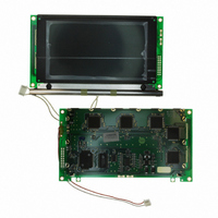
... User’s Guide NHD-240128WG-AFTI-VZ#-C5 LCM (Liquid Crystal Display Graphic Module) RoHS Compliant Newhaven Display NHD- 240 x 128 pixels 240128- WG- W= Factory Line G= Display Mode: Graphic A- Model/Serial Number White CCFL B/L F- FSTN-(negative) T- Transmissive, 6:00 View, Wide Temperature (-20 ~ +70c) I- Built-in Negative voltage, RoHS Compliant ...
Page 2
Contents 1.Module Classification Information 2.Precautions in use of LCD Modules 3.General Specification 4.Absolute Maximum Ratings 5.Electrical Characteristics 6.Optical Characteristics 7.Interface Description 8.Contour Drawing 9. Display Control Instruction 10.Timing Characteristics 11. Reliability 12.Backlight Information 13. Inspection specification 14. Material List of ...
Page 3
... Classification Information NHD 240128 Brand Newhaven Display d Display Font 240 x 128 Dots e Factory Line Display Type H Character Type, G Graphic Type Model / Serial number = A h Backlight Type N Without backlight B EL, Blue green D EL, Green W EL, White F Y LED, Yellow Green i LCD Mode ...
Page 4
LCD Modules (1)Avoid applying excessive shocks to the module or making any alterations or modifications to it. (2)Don’t make extra holes on the printed circuit board, modify its shape or change the components of LCD module. ...
Page 5
Maximum Ratings Item Operating Temperature Storage Temperature Input Voltage Supply Voltage For Logic Supply Voltage For LCD Negative Voltage Output 5.Electrical Characteristics Item Supply Voltage For Logic Supply Voltage For LCD Input High Volt. Symbol ...
Page 6
Input Low Volt. Output High Volt. Output Low Volt. Supply Current 6.Optical Characteristics Item View Angle Contrast Ratio Response Time Definition of Operation Voltage (Vop = Symbol Condition ...
Page 7
Selected Wave Intensity 100 Cr Max Vop [positive type] Conditions : Operating Voltage : Vop Frame Frequency : 64 HZ Definition of viewing angle( 270 7.Interface Description Non-selected Conition Non-selected Wave Intensity Cr = Lon / Loff 100 ...
Page 8
Pin No. Symbol Level Vss 3 Vdd C/D 9 Vee 10 RESET 11 DB0 12 DB1 13 DB2 14 DB3 15 DB4 16 DB5 17 DB6 18 DB7 ...
Page 9
effective area of LCD window of bezel. 4.0 0.5 0. MPU CE C/D 80 series or RESET 68 series DB0~DB7 Font 6X8 8X8 ...
Page 10
MPU interface, it has a 128-word character generator ROM ( refer to Table 1. ), which can control an external display RAM bytes. Allocation of text, graphics and ...
Page 11
Status check The Status of T6963C can be read from the data lines C The T6963C status word format is as follows: MSB STA7 STA6 STA5 ...
Page 12
When using the MSB=0 command, a Status Read must be performed status check is not carried out, the T6963C cannot operate normally, even after a delay time. The hardware interrupt occurs during the address calculation period ...
Page 13
COMMAND DEFINITIONS COMMAND CODE 00100001 REGISTERS SETTING 00100010 00100100 01000000 01000001 SET CONTROL WORD 01000010 01000011 1000×000 1000×001 1000×011 MODE SET 1000×100 10000××× 10001××× 10010000 1001××10 1001××11 DISPLAY MODE 100101×× 100110×× 100111×× 10100000 10100001 10100010 CURSOR PATTERN 10100011 SELECT 10100100 ...
Page 14
Setting registers CODE HEX. FUNCTION 00100001 21H SET CURSOR POINTER 00100010 23H SET OFFSET REGISTER 00100100 24H SET ADDRESS POINTER (1) Set Cursor ...
Page 15
External generator mode. The senior five bits define the start address in external memory of the CG RAM area. The next eight bits represent the character code of the character. In internal CG ROM, character codes 00H to 7FH represent ...
Page 16
RAM. (3) Set Address Pointer The Set Address Pointer command is used to indicate the start address for writing to (or reading from)external RAM. The Flowchart for Set Address Pointer command ...
Page 17
Set Control Word CODE HEX. FUNCTION 01000000 40H Set Text Home Address (upper 8 bits) D1 Low address D2 High address ...
Page 18
Set Text Area 01000010 42H Set Graphic Home Address 01000011 43H Set Graphic Area The home address and column size are defined by this command. (1) Set Text Home Address The starting address in the external display RAM ...
Page 19
Set Graphic Home Address The starting address of the external display RAM used for graphic display is defined by this command. The graphic home address indicates the leftmost and uppermost position. The relationship between external display RAM address and ...
Page 20
Set Text Area The display columns are defined by the hardware Setting. This command can be used to adjust the columns of the ...
Page 21
Set 32 columns, 2 Lines 0000 0001 0014 0015 0028 0029 003C 003D 0050 0051 0064 0065 0078 0079 008C 008D 00A0 00A1 00B4 00B5 00C8 00C9 00DC 00DD 00F0 00F1 0104 0105 0128 0129 013C 013D LCD If the ...
Page 22
The logical OR, EXOR, AND of text or graphic display can be displayed. In Internal Character Generator mode, character codes 00H to 7FH are assigned to the built-in character generator ROM. The character codes 80H to FFH ...
Page 23
Display mode CODE FUNCTION 10010000 Display off 1001xx10 Cursor on, blink off Cursor on, blink on 1001xx11 100101xx Text on, graphic off 100110xx Text off, graphic on 100111xx Text on, graphic on (Note necessary to turn on “Text ...
Page 24
When cursor display is ON, this command selects the cursor pattern in the range 1 line to 8 lines. The cursor address is defined by the Cursor Pointer ...
Page 25
...
Page 26
...
Page 27
Date Read/Write CODE HEX. FUNCTION 11000000 C0H Data Write and Increment ADP 11000001 C1H Data Read and Increment ADP 11000010 C2H Data Write and Decrement ADP 11000011 C3H Data Read and Decrement ADP 11000100 C4H Data Write and Nonvariable ADP ...
Page 28
Screen Peek CODE HEX. FUNCTION 11100000 E0H Screen Peek This command is used to transfer 1 byte of displayed data to the data stack; this byte can then be read from the MPU by data access. The logical combination of ...
Page 29
Screen Copy CODE HEX. FUNCTION 11101000 E8H Screen Copy This command copies a single raster line of data to the graphic area. The start point must be set using the Set Address Pointer command. (Note 1) If the attribute function ...
Page 30
Bit Set/Reset CODE FUNCTION 11110xxx Bit Reset 11111xxx Bit Set Bit 0 (LSB) 1111x000 1111x001 Bit 1 OPERAND ...
Page 31
Bit 2 1111x011 Bit 3 1111x100 Bit 4 1111x101 Bit 5 1111x110 Bit 6 Bit 7 (MSB) 1111x111 This command use to set or reset a bit of the byte specified by the address pointer. Only one bit can ...
Page 32
...
Page 33
Characteristics Bus Timing ( Item C/D Set-up Time C/D Hold Time CE, RD, WR Pulse Width Data Set-up Time Data Hold Time Access Time Output Hold Time ...
Page 34
Content of Reliability Test (wide temperature, -20 ~70 ) Test Item High Temperature Endurance test applying the high storage temperature storage for a long time. Low Temperature Endurance test applying the high storage temperature storage for a long time. ...
Page 35
Information No shall be lighted at constant lamp current ( and shall be measured 3 minutes after the table below. The measurement shall be conducted on the condition that ambient temperature ...
Page 36
CCFL B\L drives directly from 13. Inspection specification NO Item 1.1 Missing vertical, horizontal segment, segment contrast defect. 1.2 Missing character , dot or icon. 1.3 Display malfunction. Electrical 1.4 No function or no display. 01 Testing ...
Page 37
If bubbles are visible, judge using black spot specifications, not easy Polarizer to find, must check in 04 bubbles specify direction. NO Item 05 Scratches Follow NO.3 LCD black spots, white spots, contamination Length Width Acceptable Q TY --- Accept ...
Page 38
Symbols Define: x: Chip length k: Seal width L: Electrode pad length: 6.1 General glass chip : 6.1.1 Chip on panel surface and crack between panels: Chipped 06 glass NO Item y: Chip width z: Chip thickness t: Glass thickness ...
Page 39
Chip length k: Seal width L: Electrode pad length 6.2 Protrusion over terminal : 6.2.1 Chip on electrode pad : Glass 06 crack y: Chip width z: Chip thickness t: Glass thickness a: LCD side length 2.5 ...
Page 40
NO Item 07 Cracked glass Backlight 08 elements 09 Bezel The height of the COB should not exceed the height indicated in the assembly diagram. 10.4 There may not be more than 2mm of sealant outside the seal area on ...
Page 41
Soldering NO Item General 12 appearance Criterion 2.5 2.5 2.5 0.65 AQL 2.5 0.65 2.5 2.5 2.5 2.5 2.5 0.65 0.65 0.65 0.65 ...
Page 42
... Material List of Components for RoHs 1. Newhaven Display Intl. hereby declares that all of or part of products (with the mark “#”in code), including, but not limited to, the LCM, accessories or packages, manufactured and/or delivered to your company (including your subsidiaries and affiliated company) directly or indirectly by our company (including our subsidiaries or affiliated companies) do not intentionally contain any of the substances listed in all applicable EU directives and regulations, including the following substances ...
Page 43
RoHS requirement (1) Use the Sn/Ag/Cu soldering surface the surface of Pb-free solder is rougher than we used before. (2) Heat-resistance temp. Reflow 250 ,30 seconds Max. Connector soldering wave or hand soldering 320 , 10 seconds max. ...