HDSP-2533 Avago Technologies US Inc., HDSP-2533 Datasheet - Page 12
HDSP-2533
Manufacturer Part Number
HDSP-2533
Description
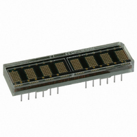
LED DISPLAY 5X7 8CHAR 5MM GREEN
Manufacturer
Avago Technologies US Inc.
Series
HDSP-253xr
Datasheet
1.HDSP-2533.pdf
(15 pages)
Specifications of HDSP-2533
Display Type
Alphanumeric
Common Pin
*
Package / Case
28-DIP
Color
Green
Size / Dimension
1.69" x .45" (42.9mm x 11.4mm)
Number Of Digits/alpha
8
Digit/alpha Size
0.20" (5mm)
Number Of Digits
8
Character Size
2.54 mm x 4.57 mm
Illumination Color
Green
Wavelength
574 nm
Operating Voltage
5 V
Operating Current
370 mA
Maximum Operating Temperature
+ 85 C
Minimum Operating Temperature
- 40 C
Luminous Intensity
7.5 ucd
Viewing Area (w X H)
40.06 mm x 4.57 mm
Lead Free Status / RoHS Status
Lead free / RoHS Compliant
Lead Free Status / RoHS Status
Lead free / RoHS Compliant, Lead free / RoHS Compliant
Other names
516-1169-5


Self Test Function (Bits 5, 6)
Bit 6 of the Control Word Register is used to initiate the self
test function. Results of the internal self test are stored in
bit 5 of the Control Word. Bit 5 is a read only bit where bit
5 = “1” indicates a passed self test and bit 5 = “0” indicates
a failed self test.
Setting bit 6 to a logic 1 will start the self test function.
The built-in self test function of the IC consists of two
internal routines which exercises major portions of the
IC and illuminates all of the LEDs. The first routine cycles
the ASCII decoder ROM through all states and performs a
checksum on the output. If the checksum agrees with the
correct value, bit 5 is set to “ 1. ” The second routine provides
a visual test of the LEDs using the drive circuitry. This is ac-
complished by writing checkered and inverse checkered
patterns to the display. Each pattern is displayed for
approximately 2 seconds.
During the self test function the display must not be
accessed. The time needed to execute the self test
function is calculated by multiplying the clock period by
262,144. For example, assume a clock frequency of 58 KHz,
then the time to execute the self test function frequency is
equal to (262,144/58,000) = 4.5 second duration.
At the end of the self test function, the Character RAM
is loaded with blanks, the Control Word Register is set to
zeros except for bit 5, and the Flash RAM is cleared and the
UDC Address Register is set to all ones.
Clear Function (Bit 7)
Bit 7 of the Control Word will clear the Character RAM
and the Flash RAM. Setting bit 7 to a “1” will start the
clear function. Three clock cycles (110 ms min. using the
internal refresh clock) are required to complete the clear
function. The display must not be accessed while the
display is being cleared. When the clear function has been
completed, bit 7 will be reset to a “0. ” The ASCII character
code for a space (20H) will be loaded into the Character
RAM to blank the display and the Flash RAM will be loaded
with “1”s. The UDC RAM, UDC Address Register and the re-
mainder of the Control Word are unaffected.
12
Display Reset
Figure 7 shows the logic levels needed to reset the display.
The display should be reset on Power-up. The external
Reset clears the Character RAM, Flash RAM, Control Word
and resets the internal counters. After the rising edge of
the Reset signal, three clock cycles (110 ms min. using the
internal refresh clock) are required to complete the reset
sequence. The display must not be accessed while the
display is being reset. The ASCII Character code for a space
(20H) will be loaded into the Character RAM to blank
the display. The Flash RAM and Control Word Register
are loaded with all “0”s. The UDC RAM and UDC Address
Register are unaffected. All displays which operate with
the same clock source must be simultaneously reset to
synchronize the Flashing and Blinking functions.
Mechanical Considerations
The HDSP-253X is assembled by die attaching and wire
bonding 280 LED chips and a CMOS IC to a thermally con-
ductive printed circuit board. A polycarbonate lens placed
over the pcb creates an air gap over the LED wire bonds. A
backfill epoxy seals the display package.
Figure 8 shows the proper method to insert the display
by hand. To prevent damage to the LED wire bonds, apply
pressure uniformly with fingers located at both ends of
the part. Using a tool, shown in Figure 9, such as a screw-
driver or pliers to push the display into the printed circuit
board or socket may damage the LED wire bonds. The
force exerted by a screwdriver is sufficient to push the lens
into the LED wire bonds. The bent wire bonds cause shorts
or opens that result in catastrophic failure of the LEDs.
Note:
If RST, CE, and WR are low, unkown data may be written into the display.
Figure 7. Logic levels to reset the display.
RST
0 = LOGIC 0; 1 = LOGIC 1; X = DO NOT CARE
0
CE
1
WR
X
RD
X
FL
X
A
4
X
-A
0
D
7
X
-D
0
Related parts for HDSP-2533
Image
Part Number
Description
Manufacturer
Datasheet
Request
R

Part Number:
Description:
LED 7-SEG 7.6MM CC HE RED RHD
Manufacturer:
Avago Technologies US Inc.
Datasheet:

Part Number:
Description:
LED 7-SEG 7.6MM CA HE RED RHD
Manufacturer:
Avago Technologies US Inc.
Datasheet:

Part Number:
Description:
Seven-Segment Numeric LED Display,2-CHARACTER,Red,DIP
Manufacturer:
Avago Technologies US Inc.
Datasheet:

Part Number:
Description:
Seven-Segment Numeric LED Display,2-CHARACTER,Green,DIP
Manufacturer:
Avago Technologies US Inc.
Datasheet:
Part Number:
Description:
Seven-Segment Numeric LED Display,2-CHARACTER,Green,DIP
Manufacturer:
Avago Technologies US Inc.
Datasheet:
Part Number:
Description:
Seven-Segment Numeric LED Display,2-CHARACTER,Red,DIP
Manufacturer:
Avago Technologies US Inc.
Datasheet:
Part Number:
Description:
Seven-Segment Numeric LED Display,2-CHARACTER,Green,DIP
Manufacturer:
Avago Technologies US Inc.
Datasheet:

Part Number:
Description:
Seven-Segment Numeric LED Display,2-CHARACTER,Orange-Red,DIP
Manufacturer:
Avago Technologies US Inc.
Datasheet:

Part Number:
Description:
LED 7-SEG 14.2MM 2DIG CC HER RHD
Manufacturer:
Avago Technologies US Inc.
Datasheet:

Part Number:
Description:
LED 7-SEG 14.2MM 2DIG CC HER RHD
Manufacturer:
Avago Technologies US Inc.
Datasheet:

Part Number:
Description:
LED 7-SEG 14.2MM 2DIG CA HER RHD
Manufacturer:
Avago Technologies US Inc.
Datasheet:

Part Number:
Description:
LED 7-SEG 14.2MM 2DIG CA GRN RHD
Manufacturer:
Avago Technologies US Inc.
Datasheet:

Part Number:
Description:
LED 7-SEG 14.2MM 2DIG CC GRN RHD
Manufacturer:
Avago Technologies US Inc.
Datasheet:

Part Number:
Description:
LED 7-SEG 14.2MM 2DIG CA GRN RHD
Manufacturer:
Avago Technologies US Inc.
Datasheet:

Part Number:
Description:
LED 7-SEG 14.2MM 2DIG CC GRN RHD
Manufacturer:
Avago Technologies US Inc.
Datasheet: