SCE5744 OSRAM Opto Semiconductors Inc, SCE5744 Datasheet - Page 11
SCE5744
Manufacturer Part Number
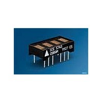
SCE5744
Description
DISPLAY 4CHAR 5X7 SER HE GRN DIP
Manufacturer
OSRAM Opto Semiconductors Inc
Series
Intelligent Display®r
Datasheet
1.SCE5744P.pdf
(16 pages)
Specifications of SCE5744
Millicandela Rating
180µcd
Size / Dimension
0.78" L x 0.40" W x 0.20" H (19.91mm x 10.16mm x 5.08mm)
Color
Green
Configuration
5 x 7
Number Of Digits
4
Character Size
0.18 in
Illumination Color
High Efficiency Green
Wavelength
568 nm
Maximum Operating Temperature
+ 85 C
Minimum Operating Temperature
- 40 C
Luminous Intensity
180 ucd
Viewing Area (w X H)
2.54 mm x 4.57 mm
Display Type
5 x 7 Dot Matrix
Lead Free Status / RoHS Status
Lead free / RoHS Compliant
Voltage - Forward (vf) Typ
-
Internal Connection
-
Lead Free Status / Rohs Status
Details
Other names
Q68100A1373
Available stocks
Company
Part Number
Manufacturer
Quantity
Price
Company:

Part Number:
SCE5744
Manufacturer:
HIROSE
Quantity:
1 000


Electrical and Mechanical Considerations
Thermal Considerations
Optimum product performance can be had when the following
electrical and mechanical recommendations are adopted. The IC
is constructed in a high speed CMOS process, consequently noise
on the SERIAL DATA, SERIAL DATA CLOCK, LOAD and RESET
lines may cause incorrect data to be written into the serial shift reg-
ister. Adhere to transmission line termination procedures when
using fast line drivers and long cables (> 10 cm).
Good ground and power supply decoupling will insure that
I
ground bounce. Therefore it is recommended that each display
package use a 0.1 µmF and 0 µF capacitor between V
ground.
When the internal MUX Clock is being used connect the CLKSEL
pin to V
nected to the system’s reset control, it is recommended that this
pin be connected to the center node of a series 0.1 µF and 100 kΩ
RC network. Thus upon initial power up the RESET will be held
low for 10 ms allowing adequate time for the system power supply
to stabilize.
ESD Protection
The input protection structure of the SCE574x provides significant
protection against ESD damage. It is capable of withstanding dis-
charges greater than 2.0 kV. Take all the standard precautions,
normal for CMOS components. These include properly grounding
personnel, tools, tables, and transport carriers that come in con-
tact with unshielded parts. If these conditions are not, or cannot be
met, keep the leads of the device shorted together or the parts in
anti-static packaging.
Soldering Considerations
The SCE574x can be hand soldered with SN63 solder using a
grounded iron set to 260°C.
Wave soldering is also possible following these conditions: Pre-
heat that does not exceed 93°C on the solder side of the PC board
or a package surface temperature of 85°C. Water soluble organic
acid flux (except carboxylic acid) or rosin-based RMA flux without
alcohol can be used.
Wave temperature of 245°C ± 5°C with a dwell between 1.5 sec. to
3.0 sec. Exposure to the wave should not exceed temperatures
above 260°C for five seconds at 1.59 mm (0.063") below the seating
plane. The packages should not be immersed in the wave.
Post Solder Cleaning Procedures
The least offensive cleaning solution is hot D.I. water (60 °C) for
less than 15 minutes. Addition of mild saponifiers is acceptable. Do
not use commercial dishwasher detergents.
For faster cleaning, solvents may be used. Exercise care in choos-
ing solvents as some may chemically attack the nylon package.
For further information refer to Appnotes 18 and 19.
An alternative to soldering and cleaning the display modules is to
use sockets. Naturally, 14 pin DIP sockets 7.62 mm (0.300”) wide
with 2.54 mm (0.100") centers work well for single displays. Multi-
ple display assemblies are best handled by longer SIP sockets or
DIP sockets when available for uniform package alignment.
Optical Considerations
The 4.57 mm (0.180") high character of the SCE574x gives read-
ability up to five feet. Proper filter selection enhances readability
over this distance.
2006-03-30
CC
(< 400 mA peak) switching currents do not generate localized
CC
. In those applications where RESET will not be con-
SCE5740, SCE5741, SCE5742, SCE5743, SCE5744, SCE5745
CC
and
11
Using filters emphasizes the contrast ratio between a lit LED and
the character background. This will increase the discrimination of
different characters. The only limitation is cost. Take into consider-
ation the ambient lighting environment for the best cost/benefit
ratio for filters.
Incandescent (with almost no green) or fluorescent (with almost no
red) lights do not have the flat spectral response of sunlight. Plas-
tic band-pass filters are an inexpensive and effective way to
strengthen contrast ratios. The SCE5740 is a red display and
should be used with long wavelength pass filter having a sharp
cut-off in the 600 nm to 620 nm range. The SCE5742 is a
super-red display and should be used with long wavelength pass
filter having a sharp cut-off in the 570 nm to 600 nm range. The
SCE5744 is a high efficiency green display and should be used
with long wavelength pass filter that peaks at 565 nm.
Additional contrast enhancement is gained by shading the
displays. Plastic band-pass filters with built-in louvers offer the next
step up in contrast improvement. Plastic filters can be improved
further with anti-reflective coatings to reduce glare.
Optimal filter enhancements are gained by using circular polar-
ized, anti-reflective, band-pass filters. The circular polarizing fur-
ther enhances contrast by reducing the light that travels through
the filter and reflects back off the display to less than 1%.
Several filter manufacturers supply quality filter materials. Some of
them are: Panelgraphic Corporation, W. Caldwell, NJ; SGL Homa-
lite, Wilmington, DE; 3M Company, Visual Products Division, St.
Paul, MN; Polaroid Corporation, Polarizer Division, Cambridge,
MA; Marks Polarized Corporation, Deer Park, NY, Hoya Optics,
Inc., Fremont, CA.One last note on mounting filters: recessing dis-
plays and bezel assemblies is an inexpensive way to provide a
shading effect in overhead lighting situations. Several Bezel manu-
facturers are: R.M.F. Products, Batavia, IL; Nobex Components,
Griffith Plastic Corp., Burlingame, CA; Photo Chemical Products of
California, Santa Monica, CA; I.E.E.-Atlas, Van Nuys, CA. The
trade-off is fuzzy characters. Mounting the filters close to the dis-
play reduces this effect. Take care not to overheat the plastic filter
by allowing for proper air flow.
Microprocessor Interface
The microprocessor interface is through the serial port, SPI port or
one out of eight data bits on the eight bit parallel port and also con-
trol lines SDCLK and LOAD.
Power Up Sequence
Upon power up display will come on at random. Thus the display
should be reset at power-up. The reset will set the Address Regis-
ter to Digit 0, User RAM is set to 0 (display blank) the Control Word
is set to 0 (100% brightness) and the internal counters are reset.
Related parts for SCE5744
Image
Part Number
Description
Manufacturer
Datasheet
Request
R

Part Number:
Description:
INTELLIGENT DISP 4CHAR 5X7 HERED
Manufacturer:
OSRAM Opto Semiconductors Inc
Datasheet:

Part Number:
Description:
DISPLAY 8DIGIT CERAMIC GREEN
Manufacturer:
OSRAM Opto Semiconductors Inc
Datasheet:

Part Number:
Description:
EMITTER IR 950NM 5MM SMD RADIAL
Manufacturer:
OSRAM Opto Semiconductors Inc
Datasheet:

Part Number:
Description:
LED TOPLED GREEN 570NM 2-PLCC
Manufacturer:
OSRAM Opto Semiconductors Inc
Datasheet:

Part Number:
Description:
INTERRUPTER RELFECT W/FILTR SMD
Manufacturer:
OSRAM Opto Semiconductors Inc
Datasheet:

Part Number:
Description:
LED Displays 5x7 Green 0.145 , 4-CHARACTER
Manufacturer:
OSRAM Opto Semiconductors Inc
Datasheet:

Part Number:
Description:
Q65110A4321_SIDELED PURE GREEN EOL150407
Manufacturer:
OSRAM Opto Semiconductors Inc
Datasheet:
Part Number:
Description:
Q65110A1202_RO DETECTOR 3/5MM_TR_RO
Manufacturer:
OSRAM Opto Semiconductors Inc
Datasheet:

Part Number:
Description:
PHOTODIODE 900NM 3MM W/FILTER
Manufacturer:
OSRAM Opto Semiconductors Inc
Datasheet:
Part Number:
Description:
INTELLIGENT DISP 4CHAR 5X7 HERED
Manufacturer:
OSRAM Opto Semiconductors Inc
Datasheet:
Part Number:
Description:
LED TOPLED GREEN 570NM 2-PLCC
Manufacturer:
OSRAM Opto Semiconductors Inc
Datasheet:
Part Number:
Description:
PHOTODIODE 900NM 3MM W/FILTER
Manufacturer:
OSRAM Opto Semiconductors Inc
Datasheet:

Part Number:
Description:
PHOTODIODE 850NM THRU-HOLE
Manufacturer:
OSRAM Opto Semiconductors Inc
Datasheet:

Part Number:
Description:
PHOTODIODE 880NM W/FILTER SMD
Manufacturer:
OSRAM Opto Semiconductors Inc
Datasheet: