HLMP-K105 Avago Technologies US Inc., HLMP-K105 Datasheet
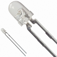
LED 3MM 645NM RED WATER CLEAR

HLMP-K105

Manufacturer Part Number
HLMP-K105
Description
LED 3MM 645NM RED WATER CLEAR
Manufacturer
Avago Technologies US Inc.
Type
Uni-Colorr
Datasheet

Specifications of HLMP-K105

Viewing Angle
45°
Package / Case
Radial - 2 Lead
Color
Red
Millicandela Rating
65mcd
Current - Test
20mA
Wavelength - Dominant
637nm
Wavelength - Peak
645nm
Voltage - Forward (vf) Typ
1.8V
Lens Type
Clear
Lens Style/size
Round, 3mm, T-1
Height
4.70mm
Mounting Type
Through Hole
Resistance Tolerance
637nm
Led Size
T-1
Illumination Color
Red
Lens Color/style
Water Clear
Operating Voltage
1.8 V
Wavelength
645 nm
Luminous Intensity
65 mcd
Mounting Style
Through Hole
Package Type
T-1
Emitting Color
Red
Test Current (it)
20mA
Forward Current
30mA
Dominant Wave Length
637nm
Forward Voltage
2.2V
Product Length (mm)
3.43mm
Product Height (mm)
4.7mm
Product Depth (mm)
3.43mm
Mounting
Through Hole
Peak Wavelength
645nm
Shape Type
Circular
Chip Material
GaAlAs
Main Category
Standard LED
Number Of Elements
1
Pin Count
2
Operating Temperature Classification
Commercial
Operating Temp Range
-20C to 100C
Reverse Voltage
5V
Power Dissipation
87mW
Lens Dimensions
3.17x3.17x3.56mm
Lead Free Status / RoHS Status
Lead free / RoHS Compliant
Luminous Flux @ Current - Test
-
Lead Free Status / Rohs Status
Lead free / RoHS Compliant
Other names
516-1314

Available stocks

Company
Part Number
Manufacturer
Quantity
Price
Part Number:
HLMP-K105
Manufacturer:
QUALITYT
Quantity:
500
Part Number:
HLMP-K105
Manufacturer:
AVAGO
Quantity:
40 000
Part Number:
HLMP-K105-J0002
Manufacturer:
AVAGO
Quantity:
40 000
Part Number:
HLMP-K105-J0002
Manufacturer:
AVAGO
Quantity:
50 000
HLMP-D101/D105, HLMP-K101/K105
T-1
High Intensity, Double Heterojunction
AlGaAs Red LED Lamps
Data Sheet
Description
These solid state LED lamps utilize newly developed
double heterojunction (DH) AlGaAs/GaAs material tech-
nology. This LED material has outstanding light output
efficiency over a wide range of drive currents. The color is
deep red at the dominant wavelength of 637 nanometres.
These lamps may be DC or pulse driven to achieve desired
light output.
Package Dimensions
3
/
4
(5 mm), T-1 (3 mm),
A
B
Features
• Exceptional brightness
• Wide viewing angle
• Outstanding material efficiency
• Low forward voltage
• CMOS/MOS compatible
• TTL compatible
• Deep red color
Applications
• Bright ambient lighting conditions
• Moving message panels
• Portable equipment
• General use
1.52 (0.060)
1.02 (0.040)
(0.95)
6.35 (0.250)
5.58 (0.220)
24.1
CATHODE
MIN.
C
SHOULDER
3.43 (0.135)
2.92 (0.115)
3.17 (0.125)
2.67 (0.105)
2.79 (0.110)
2.29 (0.090)
0.65 (0.026) MAX.
0.55 (0.022)
0.40 (0.016)
1.14 (0.045)
0.51 (0.020)
4.70 (0.185)
4.19 (0.165)
SQ. TYP.

Related parts for HLMP-K105

HLMP-K105 Summary of contents

Page 1

... HLMP-D101/D105, HLMP-K101/K105 3 T mm), T-1 (3 mm), 4 High Intensity, Double Heterojunction AlGaAs Red LED Lamps Data Sheet Description These solid state LED lamps utilize newly developed double heterojunction (DH) AlGaAs/GaAs material tech- nology. This LED material has outstanding light output efficiency over a wide range of drive currents. The color is deep red at the dominant wavelength of 637 nanometres ...

Page 2

... T-1 3/4 Red Untinted Non-diffused T-1 Red Tinted Diffused T-1 Red Untinted Non-diffused Note: 1. θ is the off axis angle from lamp centerline where the luminous intensity is 1/2 Part Numbering System HLMP - Luminous Intensity Iv (mcd Device HLMP- Min. Typ. D101 35.2 70.0 D101-J00xx 35 ...

Page 3

... The dominant wavelength, λ derived from the CIE chromaticity diagram and represents the color of the device The radiant intensity watts per steradian, may be found from the equation I e luminous efficacy in lumens/watt. 3. HLMP-D101. 4. HLMP-D105. 5. HLMP-K101/-K105. 3 [4] Min. Typ. Max. 1.8 2.2 5.0 15 ...

Page 4

Figure 1. Relative intensity vs. wavelength. Figure 3. Relative luminous intensity vs. dc forward current. Figure 5. Maximum forward dc current vs. ambient temperature. Derating based on T MAX. = 110° Figure 2. Forward current vs. forward voltage. ...

Page 5

... Figure 7. Relative luminous intensity vs. angular displacement. HLMP-D101. Figure 9. Relative luminous intensity vs. angular displacement. HLMP-D105. 5 Figure 8. Relative luminous intensity vs. angular displacement. HLMP-K101. Figure 10. Relative luminous intensity vs. angular displacement. HLMP-K105. ...

Page 6

Intensity Bin Limits Intensity Range (mcd) Color Bin Min. Red I 24.8 J 39 101.5 N 162 234.6 Q 340 540.0 T 850 1200.0 W 1700 2400.0 Z ...

Page 7

Precautions: Lead Forming: • The leads of an LED lamp may be preformed or cut to length prior to insertion and soldering on PC board. • For better control recommended to use proper tool to precisely form and ...

Page 8

Example of Wave Soldering Temperature Profile for TH LED TURBULENT WAVE 250 200 150 100 50 PREHEAT For product information and a complete list of distributors, please go to our web site: Avago, Avago Technologies, ...

Related keywords