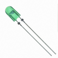
HLMP-AM87-TW000 Avago Technologies US Inc., HLMP-AM87-TW000 Datasheet

HLMP-AM87-TW000
Specifications of HLMP-AM87-TW000
Available stocks
Related parts for HLMP-AM87-TW000
HLMP-AM87-TW000 Summary of contents
Page 1
... HLMP-AD85, HLMP-AD87, HLMP-AM86, HLMP-AM87, HLMP-AB86, HLMP-AB87 Precision Optical Performance �e��� �reen an� �l�e 5mm Mini Oval ���s ���s Data Sheet Description These Precision Optical Performance Oval LEDs are specifically designed for full color/video and passenger information signs ...
Page 2
Package Dimensions A 8.70±0.20 .342±.008 5.20±0.2 .205±.008 0.8MAX. Epoxy Meniscus .016. B 11.50±0.20 0.453±.008 8.70±0.20 0.342±.008 5.20±0.20 0.205±.008 0.8MAX. Epoxy 0.032 ��OTES: Dimensions in Millimeters (Inches) For �lue and Green if heat-sinking application is required, the terminal for heat sink is anode. � 24.00MIN. 0.945 CATHODE LEAD NOTE 1 0.50±0.10 0.020±0.004 24.00 0.945 1.25±0.20 0.049±0.008 CATHODE LEAD 0.50±0.10 ...
Page 3
... HLMP-AD8�-RU0xx Red 630 HLMP-AM86-TW0xx Green ��� HLMP-AM8�-TW0xx Green ��� HLMP-A�86-MQ0xx �lue ��0 HLMP-A�8�-MQ0xx �lue ��0 ��otes: 1. Tolerance for luminous intensity measurement is ±1�% �. The luminous intensity is measured on the mechanical axis of the lamp package. 3. The optical axis is closely aligned with the package mechanical axis. ...
Page 4
Absolute Maximum Rating Parameters [1] DC forward current Peak pulsed forward current Power dissipation LED junction temperature Operating temperature range Storage temperature range ��otes: 1. Derate linearly as shown in figure 3 and figure �. �. Duty factor 10%, frequency 1KHz. 3. Duty factor 30%, frequency 1KHz. Electrical/Optical Characteristics T A Parameters Symbol Forward voltage Red V F Green �lue Reverse Voltage Red V R Green ...
Page 5
AlInGaP Red 1.0 0.5 0 550 600 650 700 WAVELENGTH – nm Figure 1. Relative intensity vs. wavelength 100 AMBIENT TEMPERATURE - C A Figure ...
Page 6
DC FORWARD CURRENT - mA Figure 8. Relative intensity vs. forward current 1 0.5 0 -90 -60 -30 ANGULAR DISPLACEMENT - DEGREES Figure 10. Spatial ...
Page 7
Intensity Bin Limit Table Intensity (mcd) at �0 mA �in Min Max M ��0 680 �� 680 880 P 880 11�0 Q 11�0 1�00 R 1�00 1900 S 1900 ��00 T ��00 3�00 U 3�00 ��00 V ��00 ��00 W ��00 ��00 Tolerance for each bin limit is ± 1�% � ...
Page 8
Avago Color Bin on CIE 1931 Chromaticity Diagram. 1.000 0.800 1 2 Green 0.600 0.400 0.200 5 Blue 0.000 0.000 0.100 0.200 10 1 RED 0.1 -40 - ...
Page 9
Precautions: Lead Forming: • The leads of an LED lamp may be preformed or cut to length prior to insertion and soldering on PC board. • For better control recommended to use proper tool to precisely form and cut the leads to applicable length rather than doing it manually. • If manual lead cutting is necessary, cut the leads after the soldering process. The solder connection forms a mechanical ground which prevents mechanical stress due to lead cutting from traveling into LED package. This is highly recommended for hand solder operation, as the excess lead length also acts as small heat sink. Soldering and Handling: • Care must be taken during PC� assembly and soldering process to prevent damage to the LED component. • LED component ...
Page 10
Refer to application note A���33� for more information about soldering and handling of high brightness TH LED lamps. Example of Wave Soldering Temperature Profile for TH LED TURBULENT WAVE 250 200 150 100 50 PREHEAT Ammo Packs Drawing 6.35 ± 1.30 (0.25 ± 0.0512) 9.125 ± 0.625 (0.3593 ± 0.0246) 18.00 ± 0.50 ...
Page 11
Packaging Box for Ammo Packs FROM LEFT SIDE OF BOX, ADHESIVE TAPE MUST BE FACING UPWARD. ANODE LEAD LEAVES THE BOX FIRST. Note: For InGa�� device, the ammo pack packaging box contains ESD logo. Packaging Label (i) Avago Mother Label: (Available on packaging box of ammo pack and shipping box) (1P) Item: Part Number (1T) Lot: Lot Number LPN (9D) MFG Date: ...
Page 12
PART #: Part Number LOT#: Lot Number MFG DATE: Manufacturing Date C/O: Country of Origin Customer P/N: Supplier Code: Acronyms and Definition: �I��: (i) Color bin only or VF bin only (Applicable for part number with color bins but without VF bin OR part number with VF bins and no color bin) OR (ii) Color bin incorporated with VF �in (Applicable for part number that have both color bin and VF bin) ...


