Standard Resistance Range
Total Resistance Tolerance .........................................................................±20 % or 10 % ...................................... ±10 % or 5 %
Independent Linearity .................................................................................±5 % ...................................................... ±5 %
Absolute Minimum Resistance ...................................................................2 ohms maximum .................................. 2 ohms maximum
Effective Electrical Angle ............................................................................(Linear tapers) 240 ° ± 5 ° ...................... (Linear tapers) 240 ° ± 6 °
Contact Resistance Variation .....................................................................±1 % ...................................................... ±1 % or 3 ohms (whichever is greater)
Dielectric Withstanding Voltage (MIL-STD-202, Method 301)
Insulation Resistance (500 VDC) ................................................................1,000 megohms minimum ..................... 1,000 megohms minimum
Power Rating At 70 °C (Voltage Limited By Power Dissipation or 350 VAC, Whichever Is Less)
Theoretical Resolution ................................................................................Essentially infi nite .................................. Essentially infi nite
Operating Temperature Range ...................................................................-40 °C to +125 °C .................................. -40 °C to +125 °C
Storage Temperature Range ......................................................................-55 °C to +125 °C .................................. -55 °C to +125 °C
Temperature Coeffi cient Over Storage Temperature Range ......................±1,000 ppm/°C ...................................... ±150 ppm/°C
Vibration (Single Section) ...........................................................................15 G ....................................................... 15 G
Shock (Single Section) ...............................................................................30 G ....................................................... 30 G
Load Life .....................................................................................................1,000 hours ........................................... 1,000 hours
Rotational Life (No Load) ............................................................................100,000 cycles ...................................... 100,000 cycles
Moisture Resistance (MIL-STD-202, Method 103, Condition B)
IP Rating .....................................................................................................IP 40 ...................................................... IP 40
Stop Strength
Mechanical Angle ...................................................................................................................................................................................................... 300 ° ±5 °
Torque
Single Section ................................................................................................................................................................. 0.14 to 1.06 N-cm (0.2 to 1.5 oz.-in.)
Dual Section .................................................................................................................................................................... 0.14 to 1.06 N-cm (0.2 to 1.5 oz.-in.)
Triple Section ................................................................................................................................................................... 0.35 to 1.41 N-cm (0.5 to 2.0 oz.-in.)
Quadruple Section .......................................................................................................................................................... 0.35 to 1.41 N-cm (0.5 to 2.0 oz.-in.)
Weight (Single Section).............................................................................................................................................................................. 21 grams maximum
Terminals .......................................................................................................................................................................... Printed circuit terminals or J-Hooks
Marking .......................................................................... Manufacturer’s trademark, wiring diagram, date code and resistance, manufacturer’s part number
Ganging (multiple section potentiometers) ..................................................................................................................................................... 4 cup maximum
Hardware ...........................................One lockwasher and one mounting nut is shipped with each potentiometer, except where noted in the part number.
For dimensional drawings see pages 3 & 4.
For ordering information see page 5.
NOTE: Model 81/82 performance specifi cations do not apply to units subjected to printed circuit board cleaning procedures.
1 At room ambient: +25 °C nominal and 50 % relative humidity nominal, except as noted.
Initial Electrical Characteristics
Environmental Characteristics
Mechanical Characteristics
Potentiometer Specifi cations
Linear Tapers (A, B, E, & H) ..................................................................(B & E) 1 K ohms to 1 megohm ............. (A & H) 100 ohms to 1 megohm
Audio Tapers (C, D, F, G, S, & T) .........................................................(D, G, S, & T) 1 K ohms to 1 megohm ... (C & F) 1 K ohms to 1 megohm
Sea Level ..............................................................................................1,500 VAC minimum .............................. 1,500 VAC minimum
70,000 Feet ..........................................................................................500 VAC minimum ................................. 500 VAC minimum
+70 °C Single Section Assembly .........................................................(Linear tapers) 0.5 watt .......................... (Linear tapers) 2 watts
+70 °C Multiple Section Assembly.......................................................(Linear tapers) 0.5 watt/section ............. (Linear tapers) 1 watt/section
+125 °C ................................................................................................0 watt ..................................................... 0 watt
Total Resistance Shift ...........................................................................±2 % maximum ..................................... ±2 % maximum
Voltage Ratio Shift ................................................................................±5 % maximum ..................................... ±5 % maximum
Total Resistance Shift ...........................................................................±10 % maximum ................................... ±5 % maximum
Total Resistance Shift ...........................................................................(Linear taper) 10 ohms or ..................... (All tapers) ±5 % TRS maximum
Contact Resistance Variation @ 50,000 cycles
Total Resistance Shift ...........................................................................(B & E tapers) ±10 % maximum ........... ±5 % maximum (all tapers)
Insulation Resistance (500 VDC) ..........................................................100 megohms minimum ........................ 100 megohms minimum
1/4 ” and 1/8 ” diameter shafts ......................................................................................................................................................... 45.19 N-cm (4 lb.-in.)
7/8 ” length shaft ................................................................................................................................................................................. 22.6 N-cm (2 lb.-in.)
Starting and Running Torque (Non-Locking Bushings)
Starting and Running Torque (Locking Bushings) ..................................................................................................... 0.14 to 2.82 N-cm (0.2 to 4.0 oz.-in.)
Shaft Locking Torque with Locknut @ 10 in-lb. (B & E Bushings) ........................................................................................................ 14 N-cm (20 oz-in.)
Mounting ...................................................................................................................................................................1.7-2.0 N-m (15-18 lb.-in.) maximum
(Each Additional Section) ...................................................................................................................................................................... 6 grams maximum
Soldering Condition .................................................................. Recommended hand soldering using Sn95/Ag5 no clean solder, 0.025 ” wire diameter.
(Audio taper) ..................................................................................±3 % ...................................................... ±3 %
(Linear taper) .................................................................................±2 % ...................................................... ±2 %
1
1
Maximum temperature 399 °C (750 °F) for 3 seconds. No wash process to be used with no clean fl ux.
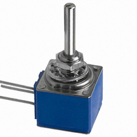
81/82 - 5/8 ” Square Single-Turn Panel Control
85/86 - 5/8 ” Square Single-Turn Panel Control with Rotary Switch
Features
■
■
■
■
Metal shaft and bushing
Consistent, smooth quality feel
Up to 4 sections available
Rotary switch option designed
for “on-off” function control
Conductive Plastic Element
(Audio tapers) 225 ° ± 5 ° ...................... (Audio tapers) 225 ° ± 6 °
(Audio tapers) 0.25 watt ........................ (Audio tapers) 1 watt
(Audio tapers) 0.25 watt/section ........... (Audio tapers) 0.5 watt/section
±10 % TRS max. (whichever is greater)
(Audio taper) ±20 % maximum
(D, G, S & T tapers) ±20 % maximum
Customers should verify actual device performance in their specifi c applications
*RoHS Directive 2002/95/EC Jan 27, 2003 including Annex.
■
RoHS compliant versions available*
Specifi cations are subject to change without notice.
Cermet Element