3364W-1-103E Bourns Inc., 3364W-1-103E Datasheet
3364W-1-103E
Manufacturer Part Number
3364W-1-103E
Description
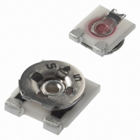
POT 10K OHM 4MM SQ CERMET SMD
Manufacturer
Bourns Inc.
Series
3364 - Open Framer
Type
Trimmerr
Datasheet
1.3364W-1-503E.pdf
(2 pages)
Specifications of 3364W-1-103E
Tolerance
±25%
Temperature Coefficient
±250ppm/°C
Resistance (ohms)
10K
Power (watts)
0.2W, 1/5W
Number Of Turns
Single
Adjustment Type
Top Adjustment
Mounting Type
Surface Mount
Resistive Material
Cermet
Package / Case
Square - 0.177" L x 0.150" W x 0.059" H (4.50mm x 3.80mm x 1.50mm)
Resistance In Ohms
10.0K
Resistance
10 KOhms
Power Rating
0.2 Watt (1/5 Watt)
Operating Temperature Range
- 40 C to + 100 C
Element Type
Cermet
Dimensions
1.5 mm W x 4.5 mm L x 3.8 mm H
Product
Trimmers
Termination Style
SMD/SMT
Taper
Linear
Tolerance (+ Or -)
25%
Technology
Cermet
Mounting Style
Surface Mount
Operating Temp Range
-40C to 100C
Failure Rate
Not Required
Shaft Diameter (mm)
3.8mm
Product Diameter (mm)
Not Requiredmm
Product Length (mm)
3.8mm
Product Height (mm)
1.5mm
Product Depth (mm)
4.5mm
Lead Free Status / RoHS Status
Lead free / RoHS Compliant
Lead Free Status / RoHS Status
Lead free / RoHS Compliant, Lead free / RoHS Compliant
Other names
3364W-103ETR
Available stocks
Company
Part Number
Manufacturer
Quantity
Price
Company:

Part Number:
3364W-1-103E
Manufacturer:
BOURNS
Quantity:
1 150


Electrical Characteristics
Standard Resistance Range
Resistance Tolerance ........... ±25 % std.
End Resistance
Contact Resistance Variation
Resolution ................................... Infi nite
Adjustment Angle ..................260 °±20 °
Environmental Characteristics
Power Rating (50 volts max.)
Temperature Range ... -40 °C to +100 °C
Temperature Coeffi cient ... ±250 ppm/°C
Humidity ................500 hours (5 % ΔTR)
Load Life .................................500 hours
Rotational Life ..... 20 cycles (15% ΔTR)
Physical Characteristics
Torque ............................ 20 to 200 g-cm
Mechanical Angle ................ Continuous
Marking ....................... Resistance code,
Terminals ......................... Solder coated
Standard Packaging ... 1000 pcs./7 ˝ reel
Adjustment Tool ..............................H-90
Aqueous cleaning not recommended.
Refl ow solder processing recommended
Model
Style
Orientation of parts in tape:
Standard Product
Resistance Code
Embossed Tape Designator
Consult factory for other available options.
*RoHS Directive 2002/95/EC Jan 27 2003 including Annex.
Specifi cations are subject to change without notice.
Customers should verify actual device performance in their specifi c applications.
How To Order
<1K ............................... 20 ohms max.
>1K ............................................... 2 %
(Voltage Divider) .................. 5 % max.
70 °C ...................................... 0.2 watt
Styles W,A
Terminals toward sprocket holes
Styles X,B
Terminals away from sprocket
holes
E = 1000 pcs./7 ” reel (-1 standard)
G = 5000 pcs./14.5 ” reel (-1 optional)
......................100 ohms to 1 megohm
manufacturer’s full part number
(see standard resistance table)
and date code on packaging
0.2 watt @ 70 °C (5 % ΔTR)
3364 X - 1 - 103 E
Features
■
■
■
TOLERANCES: ±
3364 - 4 mm Square Trimpot
Common Dimensions
3364W, X
3-Terminal
SUGGESTED PWB LAYOUT
Product Dimensions
SMD Single-Turn / Cermet / Industrial
Open Frame
Cross slot rotor designs suitable
for automatic adjustment equipment
Supplied in 12 mm embossed tape,
compatible with automatic pick-and-place
assembly equipment
(.177)
4.50
(.051)
1.30
(.022
0.55
(.079)
DIMENSIONS:
2.00
(.087)
(.094)
2.20
2.40
(.063)
1.60
(.037)
(.091)
2.30
0.95
0.15
.006)
(.055)
1.40
(.010)
(.063)
0.25
1.60
3
1
2
(.150)
3.80
1
(INCHES)
EXCEPT WHERE NOTED
(.051)
(.059)
3
1.30
1.50
MM
(.059)
1.50
(.043)
(.059)
1.10
1.50
X
X
2
(.037)
MAX.
0.95
(.039)
(.098
ADJ.
CROSS SLOT
(.022
(.014)
(.098)
1.00
0.35
2.50
2.50
(.201)
0.55
5.10
(.047)
(.031)
.12
0.80
DEEP X
.006)
LONG
0.15
.006)
.15
WIDE X
®
■
■
■
Trimming Potentiometer
3364A, B
3-Terminal
SUGGESTED PWB LAYOUT
Recommended for refl ow solder
processing only
RoHS compliant* - see
information
trimmers
For trimmer applications/processing
guidelines,
(.165)
4.20
CCW
(.047)
(.047)
1.20
1.20
(.022
0.55
(.087)
2.20
(.024)
(.079)
(.094)
(.055)
1
2.00
0.60
2.40
(.031)
1.40
(.031)
(.031)
0.80
0.80
0.80
click here
0.15
.006)
on lead free surface mount
3
(.075)
1.90
CLOCKWISE
1
(.150)
(.079)
2
3.80
2.00
2
2
(.024)
(.043)
0.60
(.059)
1.10
1.50
processing
3
WIPER
(.047)
1.20
(.059)
(.200)
1.50
5.08
(.031)
MAX.
0.80
(.098
2.50
(.020)
(.039)
1
0.50
0.99
3
0.15
.006)
(.053)
(.047)
1.35
CW
1.20
Related parts for 3364W-1-103E
Image
Part Number
Description
Manufacturer
Datasheet
Request
R

Part Number:
Description:
POT 50K OHM 4MM SQ CERMET SMD
Manufacturer:
Bourns Inc.
Datasheet:
Part Number:
Description:
POT 20K OHM 4MM SQ CERMET SMD
Manufacturer:
Bourns Inc.
Datasheet:
Part Number:
Description:
POT 1K OHM 4MM SQ CERMET SMD
Manufacturer:
Bourns Inc.
Datasheet:
Part Number:
Description:
POT 5K OHM 4MM SQ CERMET SMD
Manufacturer:
Bourns Inc.
Datasheet:
Part Number:
Description:
POT 1M OHM 4MM SQ CERMET SMD
Manufacturer:
Bourns Inc.
Datasheet:
Part Number:
Description:
POT 100K OHM 4MM SQ CERMET SMD
Manufacturer:
Bourns Inc.
Datasheet:
Part Number:
Description:
POT 2K OHM 4MM SQ CERMET SMD
Manufacturer:
Bourns Inc.
Datasheet:
Part Number:
Description:
POT 500 OHM 4MM SQ CERMET SMD
Manufacturer:
Bourns Inc.
Datasheet:
Part Number:
Description:
POT 200K OHM 4MM SQ CERMET SMD
Manufacturer:
Bourns Inc.
Datasheet:
Part Number:
Description:
RES,Cermet,500KOhms,50WVDC,25+/-% Tol,-250,250ppm-TC,1815-Case
Manufacturer:
Bourns Inc.
Datasheet:

Part Number:
Description:
Manufacturer:
Bourns, Inc.
Datasheet:
Part Number:
Description:
11mm Potentiometer
Manufacturer:
Bourns, Inc.
Datasheet:
3364W-1-103E Summary of contents
Page 1
... Open Frame ■ Cross slot rotor designs suitable for automatic adjustment equipment ■ Supplied embossed tape, compatible with automatic pick-and-place assembly equipment 3364 - 4 mm Square Trimpot Product Dimensions Common Dimensions 3364W, X 3-Terminal 3.80 (.150) 2.50 0.15 0.55 0.15 (.098 .006) (.022 ...
Page 2
Square Trimpot Packaging Specifi cations 2.20 ± 0.20 (.087 ± .008) 0.60 (.024) 5.51 ± 0.05 (.217 ± .002) 4.00 ± 0. (.157 ± .004) ORIENTATION 8.00 ± 0.10 (.315 ± .004) 2.00 ± ...