3361S-1-103GLF Bourns Inc., 3361S-1-103GLF Datasheet
3361S-1-103GLF
Manufacturer Part Number
3361S-1-103GLF
Description
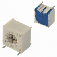
TRIMPOT 10K OHM 6MM SQ SMD
Manufacturer
Bourns Inc.
Series
3361 - Sealedr
Type
Trimmerr
Datasheet
1.3361S-1-103GLF.pdf
(2 pages)
Specifications of 3361S-1-103GLF
Tolerance
±10%
Temperature Coefficient
±100ppm/°C
Resistance (ohms)
10K
Power (watts)
0.5W, 1/2W
Number Of Turns
Single
Adjustment Type
Side Adjustment
Mounting Type
Surface Mount
Resistive Material
Cermet
Package / Case
Square - 0.264" L x 0.192" W x 0.290" H (6.71mm x 4.88mm x 7.37mm)
Resistance In Ohms
10.0K
Resistance
10 KOhms
Power Rating
0.5 Watt (1/2 Watt)
Operating Temperature Range
- 55 C to + 125 C
Element Type
Cermet
Dimensions
4.88 mm W x 6.71 mm L
Product
Trimmers
Termination Style
SMD/SMT
Voltage Rating
300 Volts
Taper
Linear
Tolerance (+ Or -)
10%
Technology
Cermet
Mounting Style
Surface Mount
Operating Temp Range
-55C to 125C
Failure Rate
Not Required
Shaft Diameter (mm)
2.77mm
Product Diameter (mm)
Not Requiredmm
Product Length (mm)
6.71mm
Product Height (mm)
7.37mm
Product Depth (mm)
6.85mm
Lead Free Status / RoHS Status
Lead free / RoHS Compliant
Lead Free Status / RoHS Status
Lead free / RoHS Compliant, Lead free / RoHS Compliant
Other names
3361S-1-103GLFTR
3361S-103GLFTR
3361S-103GLFTR


Std. Resistance Range ......10 to 2 megohms
Resistance Tolerance ............... ±10 % std.
Absolute Minimum Resistance
Contact Resistance Variation
Adjustability
Resolution ....................................... Infi nite
Insulation Resistance ................... 500 vdc.
Dielectric Strength
Adjustment Angle ..................... 240 ° nom.
Environmental Characteristics
Maximum Soldering Exposure
Power Rating (300 volts max.)
Temperature Range ....... -55 °C to +125 °C
Temperature Coeffi cient ....... ±100 ppm/°C
Seal Test ..........................85 °C Fluorinert†
Humidity ...........MIL-STD-202 Method 103
Vibration ............30 G (1 % ΔTR; 1 % ΔVR)
Shock ..............100 G (1 % ΔTR; 1 % ΔVR)
Load Life ..... 1,000 hours 0.5 watt @ 70 °C
Rotational Life ...........................200 cycles
Physical Characteristics
Mechanical Angle ..................... 270 ° nom.
Torque ................................. 3.0 oz-in. max.
Stop Strength ..................... 7.0 oz -in. min.
Terminals ........................... Solderable pins
Weight ........................................... 0.02 oz.
Marking ........................... Resistance code,
Wiper ................... 50 % (Actual TR) ±10 %
Flammability ..............................U.L. 94V-0
Standard Packaging
Adjustment Tool ..................................H-90
TOLERANCES:
Electrical Characteristics
Voltage ...................................... ±0.05 %
Resistance ................................ ±0.15 %
Sea Level ................................... 900 vac
80,000 Feet ................................ 350 vac
(Temp/Time) ..........+260 ˚C/20 sec. max.
70 °C ........................................ 0.50 watt
125 °C ........................................... 0 watt
“S” Style ...................... 500 pcs./13 ˝ reel
“P” Style ...................... 750 pcs./13 ˝ reel
........................................ 1 % or 2 ohms
............................... 3 % or 3 ohms max.
CCW
terminal numbers, manufacturer’s
DIMENSIONS:
1
(see standard resistance table)
CLOCKWISE
(.010)
(2 % ΔTR; 10 Megohms IR)
0.25
(tighter tolerance available)
(3 % ΔTR; 3 % or 3 ohms,
whichever is greater, CRV)
(4 % ΔTR; 3 % or 3 ohms,
whichever is greater, CRV)
(whichever is greater)
(whichever is greater)
2
1,000 megohms min.
model number, style
(INCHES)
EXCEPT WHERE NOTED
WIPER
MM
and date code
above 255 °C
3
96 hours
CW
Features
■
■
■
■
3361 - 1/4 ” Square SMD Trimpot
3361P
(.277 ± .010)
7.04 ± 0.25
(.192 ± .005)
(.100 ± .010)
Product Dimensions
4.88 ± 0.12
(.099 ± .010)
Recommended Land Pattern
Single-Turn / Cermet / Industrial / Sealed
Miniature package
Rotor designed for automatic machine
adjust interface
Withstands harsh environments and
immersion cleaning processes
2.51 ± 0.25
2.54 ± 0.25
(.130 ± .010)
3.30 ± 0.25
TYP.
(.264 ± .010)
6.71 ± 0.25
(.151 ± .010)
(.047 ± .005)
3.84 ± 0.25
1.19 ± 0.12
(.090 ± .0002)
3
2.29 ± .005
(.205 ± .025)
5.21 ± 0.63
TYP.
SECTION A-A
1
(.200 ± .005)
A
5.08 ± 0.12
(.090)
(.061)
2.29
1.54
(.031 ± .010)
46 °
0.79 ± 0.25
3361
2
(.015 ± .005)
(.018 ± .001)
0.46 ± 0.02
0.38 ± 0.12
3 PLACES
(.100 ± .010)
2.54 ± 0.25
1
(.035)
0.89
A
3
(.381 ± .005)
LEADS TO BE
COPLANAR
WITHIN 0.10
9.70 ± 0.12
Customers should verify actual device performance in their specifi c applications.
(.109 ± .0002)
(.336 ± .030)
8.53 ± 0.76
(.100 ± .010)
2.77 ± .005
ELECTRICAL
ADJ. SLOT
(.025)
2.54 ± 0.25
0.64
(.035)
0.89
DIA.
(.004)
WIDE
DEEP
X
*RoHS Directive 2002/95/EC Jan 27 2003 including Annex.
■
■
■
3361S
®
(.290 ± .015)
7.37 ± 0.38
Compatible with surface mount
manufacturing processes
RoHS compliant* - see
information
trimmers
For trimmer applications/processing
guidelines,
Recommended Land Pattern
Trimming Potentiometer
(.040 ± .010)
Specifi cations are subject to change without notice.
1.02 ± 0.25
(.10 ± .010)
(.028 ± .010)
2.54 ± 0.25
0.71 ± 0.25
(.047 ± .005)
1.19 ± 0.12
(.264 ± .005)
(.130 ± .010)
(.164 ± .015)
(.100 ± .010)
6.71 ± 0.12
2.54 ± 0.25
3.30 ± 0.25
4.17 ± 0.38
3 PLCS
(.090 ± .0002)
2.29 ± .005
(.100 ± .005)
click here
2.54 ± 0.12
on lead free surface mount
3 PLCS
3
TYP.
1
A
SECTION A-A
(.192 ± .010)
4.88 ± 0.25
(.262)
6.65
2
(.090)
(.061)
3361
2.29
1.54
46 °
REF.
processing
A
3
(.015 ± .002)
(.035)
0.38 ± 0.05
(.300 ± .005)
1
0.89
(.100 ± .010)
7.62 ± 0.12
(.109 ± .0002)
2.54 ± 0.25
2.77 ± .005
ELECTRICAL
ADJ. SLOT
(.025)
(.035)
0.64
0.89
(.090 ± .010)
(.090 ± .010)
2.29 ± 0.25
2.29 ± 0.25
LEADS TO BE
COPLANAR
WITHIN 0.10
WIDE
DEEP
(.004)
X
Related parts for 3361S-1-103GLF
Image
Part Number
Description
Manufacturer
Datasheet
Request
R

Part Number:
Description:
TRIMPOT 1.0K OHM 6MM SQ SMD
Manufacturer:
Bourns Inc.
Datasheet:
Part Number:
Description:
TRIMPOT 100K OHM 6MM SQ SMD
Manufacturer:
Bourns Inc.
Datasheet:
Part Number:
Description:
TRIMPOT 500 OHM 6MM SQ SMD
Manufacturer:
Bourns Inc.
Datasheet:
Part Number:
Description:
TRIMPOT 20K OHM 6MM SQ SMD
Manufacturer:
Bourns Inc.
Datasheet:
Part Number:
Description:
TRIMPOT 2.0K OHM 6MM SQ SMD
Manufacturer:
Bourns Inc.
Datasheet:
Part Number:
Description:
TRIMPOT 50K OHM 6MM SQ SMD
Manufacturer:
Bourns Inc.
Datasheet:
Part Number:
Description:
TRIMPOT 5.0K OHM 6MM SQ SMD
Manufacturer:
Bourns Inc.
Datasheet:
Part Number:
Description:
TRIMMER - 6MM SQ ST CERMET
Manufacturer:
Bourns Inc.
Datasheet:
Part Number:
Description:
TRIMPOT 50 OHM 6MM CERMET SMD
Manufacturer:
Bourns Inc.
Datasheet:
Part Number:
Description:
TRIMPOT 25K OHM 6MM CERMET SMD
Manufacturer:
Bourns Inc.
Datasheet:

Part Number:
Description:
Manufacturer:
Bourns, Inc.
Datasheet:
Part Number:
Description:
11mm Potentiometer
Manufacturer:
Bourns, Inc.
Datasheet:
3361S-1-103GLF Summary of contents
Page 1
... RoHS compliant* - see processing information on lead free surface mount trimmers ■ For trimmer applications/processing guidelines, click here ® Trimming Potentiometer 3361S 6.71 ± 0.12 (.264 ± .005) 2.77 ± .005 (.109 ± .0002) 7.37 ± 0. (.290 ± .015) 4.17 ± 0.38 ELECTRICAL (.164 ± ...
Page 2
Square SMD Trimpot How To Order 3361 502 G LF Model Style Standard or Modifi ed Product Indicator -1 = Standard Product Resistance Code Packaging Designator G = Embossed Tape “S” Style ...