UCE-12/4.2-D48NB-C Murata Power Solutions Inc, UCE-12/4.2-D48NB-C Datasheet
UCE-12/4.2-D48NB-C
Specifications of UCE-12/4.2-D48NB-C


Related parts for UCE-12/4.2-D48NB-C


UCE-12/4.2-D48NB-C Summary of contents
Page 1
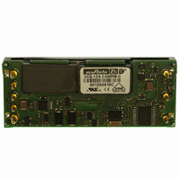
... For full details go to www.murata-ps.com/rohs Typical unit For effi cient, fully isolated DC power in the smallest space, the UCE open frame DC/DC converter series fi industry-standard “eighth brick” outline dimensions and mounting pins (on quarter-brick pinout). PRODUCT OVERVIEW Units are offered with fi xed output voltages from 1 ...
Page 2
... L2 = Pin length 0.145 inches (3.68mm)* * Special quantity order is required. , standard , optional, special quantity order Note: Some model combinations may not be available. Contact Murata Power Solutions for availability. email: sales@murata-ps.com 21 Feb 2011 MDC_UCE.A30 Page Package Typ. Case Pinout 87% C56 P32 88% 91% 90% 91% 90 ...
Page 3
... Effi ciency See ordering guide Isolation Isolation Resistance Capacitance MΩ pF Isolation Safety Rating 100 10 1000 Basic Insulation 100 email: sales@murata-ps.com 21 Feb 2011 MDC_UCE.A30 Page “N” Model Suffix OFF=open or +2.5V to +15V max. +0.8V max. Current Limit Inception 98% of Vout, after warmup A 24 ...
Page 4
... Volt input models 100 Volts +15 Volts None, install external fuse. Magnetic feedback. See specifi cations. Current-limited. Devices can withstand sustained short circuit without damage. –40 to +125°C. See soldering guidelines. email: sales@murata-ps.com 21 Feb 2011 MDC_UCE.A30 Page Relative Humidity 16 (non-condensing) to +85°C/85% ...
Page 5
... The outputs are not intended to sink appreciable reverse current. This may damage the outputs. (8) Output noise may be further reduced by adding an external fi lter. See I/O Filtering and Noise Reduction. (9) All models are fully operational and meet published specifi cations, including “cold start” nominal nominal, full load ...
Page 6
... These converters are pin-for-pin/plug- compatible to competitive units. Other units may use different pin numbering or alternate outline views. When laying out your PC board, follow the pin FUNCTION. DOSA designates Pin 1 as +Input and Pin 3 as -Input. email: sales@murata-ps.com 21 Feb 2011 MDC_UCE.A30 Page ...
Page 7
... When laying out your PC board, follow the pin FUNCTION. DOSA designates Pin 1 as +Input and Pin 3 as -Input. If not wired to an external load, the Sense inputs must be connected to their respec- tive Vout pins at the converter. email: sales@murata-ps.com 21 Feb 2011 MDC_UCE.A30 Page ...
Page 8
... Figure 2. Measuring Input Ripple Current In critical applications, output ripple and noise (also referred to as periodic and random deviations or PARD) may be reduced by adding fi lter elements such as multiple external capacitors. Be sure to calculate component tempera- ture rise from refl ected AC current dissipated inside capacitor ESR. ...
Page 9
... Linear Feet per Minute (“LFM”). Note that these are AVERAGE measurements. The converter will accept brief increases in current or reduced airfl long as the average is not exceeded. Note that the temperatures are of the ambient airfl ow, not the converter itself which is obviously running at higher temperature than the outside air. Also note that very low fl ...
Page 10
... If the short-circuit condition persists, another shutdown cycle will initiate. This rapid on/off cycling is called “hiccup mode.” The hiccup cycling reduces the average output current, thereby preventing excessive internal temperatures and/or component damage. The “hiccup” system differs from older latching short circuit systems because you do not have to power down the converter to make it restart ...
Page 11
... Low Profi le DC/DC Converters − 10.22 +VCC ON/OFF CONTROL -INPUT Figure 7. Driving the On/Off Control Pin (suggested circuit) +OUTPUT –INPUT +SENSE R TRIM DOWN ON/OFF TRIM CONTROL –SENSE +INPUT –OUTPUT Figure 8. Trim Connections To Decrease Output Voltages email: sales@murata-ps.com 21 Feb 2011 MDC_UCE.A30 Page LOAD ...
Page 12
... Output Capacitive Load These converters do not require external capacitance added to achieve rated specifi cations. Users should only consider adding capacitance to reduce switch- ing noise and/or to handle spike current step loads. Install only enough capaci- tance to achieve noise objectives. Excess external capacitance may cause regulation problems, slower transient response and possible instability ...
Page 13
... The airfl ow collimator mixes the heat from the heating ele- ment to make uniform temperature distribution. The collimator also reduces the amount of turbulence adjacent to the UUT by restoring laminar airfl ow. Such turbulence can change the effec- tive heat transfer characteristics and give false readings. Excess turbulence removes more heat from some surfaces and less heat from others, possibly causing uneven overheating ...
Page 14
... TYPICAL PERFORMANCE CURVES UCE-1.5/20-D48 Effi ciency vs Line Voltage & Load Current @ 25º Vin = 75V 80 Vin = 48V Vin = 36V Load Current (A) UCE-1.8/30-D48 Effi ciency vs Line Voltage & Load Current @ 25º Vin = 75V 80 Vin = 48V 75 Vin = 36V Load Current (A) UCE-2.5/20-D48 Effi ciency vs Line Voltage & Load Current @ 25ºC ...
Page 15
... TYPICAL PERFORMANCE CURVES UCE-3.3/15-D48 Effi ciency Vs. Line Voltage & Load Current @ +25º Vin = 75V 85 Vin = 48V Vin = 36V Load Current ( UCE-3.3/30-D48 Maximum Current Temperature Derating (Vin=48V, no baseplate, longitudinal airfl sea level 400 LFM 15 300 LFM 10 200 LFM 100 LFM 100 LFM ...
Page 16
... Vin = 75V 86 Vin = 48V 84 82 Vin = 36V Power Dissipation (Vin = 48V Load Current (A) UCE-5/20-D48 Effi ciency Effi ciency and Power Dissipation @ Ta = +25º Vin = 75V 88 Vin = 48V Vin = 36V 86 84 Power Dissipation (Vin = 48V Load Current (A) UCE-12/4.2-D48 Effi ciency Vs. Line Voltage & Load Current @ +25ºC ...
Page 17
... TYPICAL PERFORMANCE CURVES UCE-12/8.3-D48 Effi ciency vs Line Voltage & Load Current @ 25º Vin = 75V 85 Vin = 48V Vin = 36V Load Current (A) UCE-12/10-D48 Effi ciency and Power Dissipation @ Ta = +25ºC 100 Vin = 75V 75 Vin = 48V 70 Vin = 36V Power Dissipation (Vin = 48V Load Current (A) Murata Power Solutions, Inc. 11 Cabot Boulevard, Mansfi ...