HW-USB-II-G Xilinx Inc, HW-USB-II-G Datasheet
HW-USB-II-G
Specifications of HW-USB-II-G
Available stocks


Related parts for HW-USB-II-G


HW-USB-II-G Summary of contents
Page 1
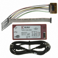
DS593 (v1.2.1) March 17, 2011 Features • High-performance FPGA and PROM programming and configuration • Includes innovative FPGA-based acceleration firmware encapsulated in a small form factor pod attached to the cable • Leverages high-speed Slave Serial mode programming interface • ...
Page 2
Compatible with Platform Cable USB and is supported by all Xilinx design tools that support Platform Cable USB. Platform Cable USB II attaches to the USB port on a desktop or laptop PC using an off-the-shelf Hi-Speed USB A–B cable. ...
Page 3
Physical Description The Platform Cable USB II electronics are housed in a recyclable, fire-retardant plastic case shield attenuates internally generated emissions and protects against susceptibility to radiated emissions. X-Ref Target - Figure 2 Top View HI-SPEED USB CERTIFIED Side View ...
Page 4
Table 1: Platform Cable USB II Software Compatibility Software ISE Foundation / ISE WebPACK ChipScope Pro Analyzer Embedded Development Kit System Generator for DSP Notes installer must be run to enable Platform Cable USB II for use with ...
Page 5
USB 2.0 port and 60 seconds over a USB 1.1 port. Reprogramming times vary depending on the Xilinx design tool version, the type of USB port and the performance of the host system. During a ...
Page 6
X-Ref Target - Figure 4 Option 2: Manual Cable Connect To manually connect the cable, select Output → Cable Setup. Select the Xilinx USB Cable radio button in the Cable Communication Setup dialog box (Figure X-Ref Target - Figure 5 ...
Page 7
If an iMPACT session is active when an Output → Cable Disconnect or Output → Disconnect All Cables operation is performed the cable is physically disconnected from the host system, the Cable Status Bar bottom, right-hand edge of ...
Page 8
BSDL file of each device in a target JTAG chain is scanned to determine the maximum Boundary-Scan clock (JTAG TCK) frequency. iMPACT 7.1i (and later) automatically restricts the available TCK_CCLK_SCK selections ...
Page 9
Cable Status Bar A status bar on the bottom edge of the iMPACT GUI example, if the host port is USB 2.0, Platform Cable USB II connects at Hi-Speed and the status bar shows usb-hs. If the host port ...
Page 10
The status LED is off whenever Platform Cable USB II enters a suspend state (see disconnected from a USB port connected to an un-powered USB port. Table 4 summarizes the various status LED states. Table 4: Interpreting the ...
Page 11
... A 6-inch ribbon cable is supplied and recommended for connection to target systems multiple signal-ground pairs and facilitates error-free connections. The Xilinx product number for the 6-inch ribbon cable is HW-RIBBON14. To take advantage of the ribbon cable, a mating connector must be incorporated into the target system. This connector is normally installed only during prototype checkout ...
Page 12
... Note: This method of connection is not recommended because it can result in poor signal integrity. Additionally, damage can result if the leads are unintentionally connected to high voltages. The Xilinx product number for the flying wire set is HW-USB-FLYLEADS-G. X-Ref Target - Figure 11 Platform Cable USB II Model DLC10 Power 5V 0 ...
Page 13
X-Ref Target - Figure 12 Figure 12: Flying Wire Adapter (Side) without Wires Physical Connection to the Host Each Platform Cable USB II includes a detachable, Hi-Speed-USB-certified, 1.8-meter A–B cable circumstances should user-supplied cables exceed 5 meters. Sub-channel cables (intended ...
Page 14
Target Interface Connectors Mating connectors for attachment of the high-performance ribbon cable to a target system are available in both through-hole and surface mount configurations (Figure orientation when inserting the cable. The connector requires only 105 mm The target system ...
Page 15
Target System Connections This section provides examples of the various configuration topologies supported by Platform Cable USB II. Each example incorporates the 2-mm connector (see provide a functional relationship between the cable interface and the target devices. Note: Signal integrity ...
Page 16
X-Ref Target - Figure 16 V TDO TDI TMS TCK (1) V CCAUX 2-mm Connector 2 V REF 8 TDO 10 TDI TMS 4 6 TCK (5) 13 PGND (2) * GND Notes: 1. Example implies that ...
Page 17
Direct SPI Platform Cable USB II can connect directly to a single SPI flash device. connection. XAPP951, Configuring Xilinx FPGAs with SPI Serial Flash provides additional details of the cable connections necessary to program a FPGA bitstream into a SPI ...
Page 18
X-Ref Target - Figure 18 +2.5V +3.3V +1.2V (2) Spartan-3E FPGA CSO_B GND PROG_B Notes: 1. The pin names for a ST Microsystems M25Pxx serial flash device are shown in this example. SPI flash devices from other vendors can have ...
Page 19
For a complete description on using Platform Cable USB II for indirect programming of third-BPI PROMs and for a complete list of supported BPI PROMs, refer to XAPP973, Indirect Programming of BPI PROMs with Virtex-5 FPGAs. Target Interface Reference Voltage ...
Page 20
X-Ref Target - Figure 19 X-Ref Target - Figure 20 FPGA Output High-Z Control DS593 (v1.2.1) March 17, 2011 Figure 19: V Current vs. V REF REF V NC7SZ126 REF_CLAMP 30.1Ω BAT54 To input buffer Figure 20: Target Interface Driver ...
Page 21
X-Ref Target - Figure 21 Input Receive Structure Each input signal is routed through a NC7WZ07 ultra high-speed CMOS, open-drain receive buffer. Series-termination resistors (499Ω) provide current limit protection for positive and negative excursions. Schottky diodes provide the input buffers ...
Page 22
Pseudo Ground Signal The pseudo ground (PGND) pin on target interface connector is routed to a ultra-high-speed buffer with an open-drain output (Figure 23). A pull-up resistor is required on target systems that utilize this signal. The buffer can tolerate ...
Page 23
X-Ref Target - Figure 24 Figure 24: Enabling the HALT Signal in iMPACT (9.2i) Timing Specifications For JTAG, SPI, and Slave Serial configuration modes, the TDI_DIN_MOSI and TMS_PROG_SS outputs change on falling edges of TCK_CCLK_SCK (Figure TCK_CCLK_SCK. The minimum setup ...
Page 24
Note: The propagation delay from TCK to TDO is 26 ns. Because is attributable exclusively to input delays in the cable MHz, there is still sufficient setup time before the cable samples prior to the next negative TCK ...
Page 25
X-Ref Target - Figure 26 Figure 26: TDO Sampling Example at 12 MHz (TDO Propagation Delay) DS593 (v1.2.1) March 17, 2011 Negative TCK transition at G1 causes target device to change TDO state, which propagates to the cable at G2 ...
Page 26
X-Ref Target - Figure 27 TDO setup time prior to internal sampling clock (G2 – G1) is 42ns in this 12-MHz example. Figure 27: TDO Sampling Example at 12 MHz (TDO Setup Time Relative to Sampling Point) DS593 (v1.2.1) March ...
Page 27
X-Ref Target - Figure 28 Propagation delay from (26 ns) captured directly at the target represents 70% of the total propagation delay seen by the cable (Figure 25). TCK TDO Figure 28: TDO Sampling Example at 12 ...
Page 28
Each differential receiver can drive multiple target devices if there are no branches on the PCB trace and the total trace length is less than four inches. A series termination resistor should be placed adjacent to the single-ended output of ...
Page 29
X-Ref Target - Figure 30 (A) 12 Mb/s Bus Speed 12 Mb/s Bus Speed 1.X Root Hub 1.X Root Hub 500 mA 2.0 External Platform Cable Bus-Powered USB II Enumerates at full speed because root hub only operates at full ...
Page 30
Table 6: JTAG/SPI/Slave Serial Port: 2-mm Connector Signals (Cont’d) MODE Pin JTAG Number Configuration Programming 10 TDI 13 PGND 14 HALT 4 – 6 – 8 – 10 – 13 – PGND 14 – 4 – 6 – DS593 (v1.2.1) ...
Page 31
Table 6: JTAG/SPI/Slave Serial Port: 2-mm Connector Signals (Cont’d) MODE Pin JTAG Number Configuration Programming 8 – 10 – 13 – 14 – – – Notes: 1. The listed SPI pin names match ...
Page 32
Table 7: Absolute Maximum Ratings Symbol Description DC Output Current (TCK_CCLK_SCK, I OUT TMS_PROG_SS, TDI_DIN_MOSI, and INIT) Notes: 1. Exposure to absolute rating conditions for extended periods of time can affect product reliability. The values listed in this table are ...
Page 33
Table 10: Switching Characteristics Symbol Description T Target Setup Time TSU (TDI or TMS relative to the positive edge of TCK) T Cable Setup Time CSU (TDO relative to the negative edge of TCK) T Target Propagation Delay Time TPD ...
Page 34
... Ribbon Cable, 6-inch Flying Wire Set HW-USB-FLYLEADS-G Marking Information Table 12: Marking Information Model Name Serial Prefix DLC10 XU DS593 (v1.2.1) March 17, 2011 Table 11 plus a 1.8-meter, Hi-Speed USB, A-B cable. Product Number HW-USB-II-G HW-RIBBON14 Description Platform Cable USB II www.xilinx.com Platform Cable USB II 34 ...
Page 35
Revision History The following table shows the revision history for this document: Date Version 03/03/08 1.0 Initial Xilinx release. 05/14/08 1.1 • Updated trademark references. • Added support for Platform Flash XL. 06/09/08 1.2 Corrected the functional descriptions of pins ...