ATEVK525 Atmel, ATEVK525 Datasheet
ATEVK525
Specifications of ATEVK525
AT89EVK525
Available stocks


Related parts for ATEVK525


ATEVK525 Summary of contents
Page 1
... ATEVK525 Mass Storage Board for AVR .............................................................................................. Hardware User Guide ...
Page 2
... ATEVK525 Mass Storage Board for AVR User Guide Section 1 Introduction ........................................................................................... 1-3 1.1 Overview ...................................................................................................1-3 1.2 ATEVK525 AVR Mass Storage Board Features .......................................1-4 Section 2 Using the ATEVK525............................................................................ 2-5 2.1 Getting started ..........................................................................................2-5 2.2 NAND Flash ..............................................................................................2-7 2.3 SD/MMC Card.........................................................................................2-11 2.4 LEDs .......................................................................................................2-12 2 ...
Page 3
... Product Name> microcontroller. This board is designed to allow an easy evaluation of USB Mass Storage using demonstration software. The ATEVK525 board has been designed to be plugged into the Atmel STK525 Starter Kit Board in order to add Mass Storage capability to an existing development board, and to combine them with other features (USB, RS232, Microphone..., but also all AVR development tools), reducing the extension board complexity and cost ...
Page 4
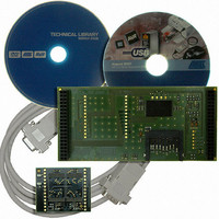
... ATEVK525 AVR Mass Storage Board Features 1-4 7740B–AVR–03/08 Figure 1-1 . ATEVK525 The ATEVK525 provides the following features: NAND Flash chip soldered (Micron MT29F2G08AACWP, 256 MBytes) Reserved location additional NAND Flash chips module plug-in Receptacle for SD and MMC memory cards ...
Page 5
... ATEVK525 Mass Storage Board for AVR This chapter describes the board and all its features. The ATEVK525 is an extension board that must be plugged on another microcontroller hosting board, like STK525 (AT90USBxxx support), that provides supply voltage. Figure 2-1 . Connecting the ATEVK525 under the STK525 ...
Page 6
... Power supply 2-6 7740B–AVR–03/08 The ATEVK525 must be powered with a voltage between 2.8 and 3.5V. Before connecting or powering the boards, you must ensure the power supply configuration on the motherboard. The voltage must be set to 3.3V (microcontroller I/O levels), and this voltage must be present on the VTG pins of the EXPAND connectors ...
Page 7
... If the supplement is not mounted or needs to be disabled, the solder pad SP1 must be soldered to connect power supply of the on-board resources (see photo above). The ATEVK525 comes with one NAND Flash chip soldered. At the time of writing, this chip is the Micron MT29F2G08AACWP that features: 2 GBits (256 MBytes) organized as: – ...
Page 8
... Note: The ‘#’ character indicates that the corresponding signal is active low. possible to install it on the ATEVK525 through an additional module as described below. The board provides two SIP-13 receptacle footprints (2.54mm pitch). Users can solder a receptacle on the board and then insert a NAND Flash module described below, or directly solder the module ...
Page 9
... ATEVK525 Mass Storage Board for AVR NFCON1 Pin # Function 4 WP0# 5 VCC 6 CLE 7 ALE 8 R/B1# 9 CE0# 10 R/B0# 11 CE1# 12 RE# 13 WE# Refer to the CD-ROM documentation if you wish to create your own PCB board and mount devices on this board (BOM and components placement). Each module can receive up to four different devices, according to the following placement : Table 2-3 ...
Page 10
... When using the additional module, check that the configuration pads that enable CTS/RTS lines on STK525 are not soldered, because these signals are also con- nected to the R/B#2 & 3. But if CTS/RTS lines are required, you cannot use the R/B#2 & 3 signals, so disable the configuration pads CP1 & CP2 of the ATEVK525. See Note 1 Function ...
Page 11
... SD/MMC Card ATEVK525 Mass Storage Board for AVR The ATEVK525 includes a receptacle compatible with SD and MMC memory cards. Figure 2 card pinout (contact view) Note: 1. The MMC card defined by specification v3.31 and earlier have only the pins # The MMC card defined by specification v4.0 and later (MMC Plus, Extra..) has 13 ...
Page 12
... SD_SCK: SD/MMC clock signal – SD_CS: SD/MMC chip select signal (active low) – NF_CLE: NAND Flash CLE signal – NF_ALE: NAND Flash ALE signal – NF_RE: NAND Flash RE# signal – NF_WE: NAND Flash WE# signal ATEVK525 Mass Storage Board for AVR ...
Page 13
... Configuration Pads 2.6.1 Configuration Pads Listing 2.6.2 Configuration Pads - Disconnection 2.6.3 Configuration Pads - Connection ATEVK525 Mass Storage Board for AVR to Configuration pads are used disconnect/connect on-board peripherals or elements. Their default configuration is: connect. Table 2-6 . Configuration Pads Config. Related Pads Signals ...
Page 14
... User may solder the pad to enable it. Table 2-7 . Solder Pads Solder. Related Pads Signals Reference This solder pad allows power protection circuit bypassing. If SP1 VCC this optional circuit is not mounted, this solder pad must be soldered. Function ATEVK525 Mass Storage Board for AVR ...
Page 15
... Software packages ATEVK525 Mass Storage Board for AVR Software Implementation This section contains information about the software package, its performance and known limitations. When you have connected the boards together and correctly checked their configuration, you are invited to run one of the available demonstration packages: USB Device External Multi Disk Drives ...
Page 16
... This package is also included on the CD-ROM as a password protected archive. Please refer to the CD-ROM documentation to know the procedure to follow to register and access the source code. Note: At first board start-up, the on-board memory chip need to be formatted by the Host oper- ating system. ATEVK525 Mass Storage Board for AVR ...
Page 17
... Performances 3.2.1 Benchmark 3.2.2 Direct limitations ATEVK525 Mass Storage Board for AVR Table 3-1 . Memory speed benchmark (8MHz clocked microcontroller Memory DataFlash AT45DB321 (page 512B) AT45DB642 (page 1024B) MMC/SD SD 1GB 80x SD 256MB MMC Plus 2GB Premium MMC 32MB (old revision) ...
Page 18
... Another feature that should be implemented next is the Recovery option. This option prevents user halts or disconnections during write operations from destroying the memory File System structure, by recovering the data lost in the last write ATEVK525 Mass Storage Board for AVR ...
Page 19
... Usage Notes 3.5 Handling another NAND Flash device ATEVK525 Mass Storage Board for AVR operations. Also, the support of more than one memory chip (facilitating memories interlacing) is not yet integrated in the driver. That also concerns memories that are made of several memory dies stacked (generaly memories of 4GBits and more). ...
Page 20
... For example, the board comes with the default configuration #define NF_TYPE_MT29F2G08AACWP – if you want to use different modules with different memory references, without modifying the driver, you NF_AUTO_DETECT_2KB or NF_AUTO_DETECT_512B, according to the page size of the memory. must enable to TRUE ATEVK525 Mass Storage Board for AVR either ...
Page 21
... ATEVK525 Mass Storage Board for AVR Troubleshooting Guide Please refer to this guide before sending a request to AVR Technical Support. Main problems should be solved here. This guide assumes that the board driver file provided by Atmel is used. Figure 4-1 . Troubleshooting Guide Reason or Problem Condition ...
Page 22
... Memory failure Problem / Solution Check the insertion direction. It can sound stupid, but that can happen to anybody... Check that the connector is not too old. Memories are not immortal...Check the memory card with another memory reader. ATEVK525 Mass Storage Board for AVR ...
Page 23
... ATEVK525 Mass Storage Board for AVR Technical Specifications System Unit – Physical Dimensions ................................................. L=119 x W=56 x H=23 mm – Weight ...........................................................................................................50 g Operating Conditions – Internal Voltage Supply ................................................................ 3.3V (+/-10%) – External Voltage Supply ................................................ 3.3V (+/-10%) (100mA) Features – NAND Flash device............................................................ MT29F2G08AACWP – MMC/SD receptacle – ...
Page 24
... ATEVK525 Mass Storage Board for AVR For Technical support, please contact avr@atmel.com. When requesting technical support, please include the following information: Which target AVR device is used (complete part number) Target voltage and speed Clock source and fuse setting of the AVR Programming method (ISP, Parallel or specific Boot-Loader) Hardware revisions of the AVR tools, found on the PCB Version number of AVR Studio ...
Page 25
... ATEVK525 Mass Storage Board for AVR On the next pages, the following documents of ATEVK525 are shown: Complete schematics, Assembly drawing, Bill of materials. Default configuration summary Section 7 Complete Schematics 7-25 7740B–AVR–03/08 ...
Page 26
... Complete Schematics PC7 PC6 PC5 PC4 PC3 PC2 PC1 PC0 7-26 7740B–AVR–03/08 Figure 7-1 . Schematics MODULE NF PA0 PA1 PA2 PA3 PA4 PA5 PA6 PA7 MODULE NF SP1 ATEVK525 Mass Storage Board for AVR ...
Page 27
... ATEVK525 Mass Storage Board for AVR Figure 7-2 . Assembly Drawing 1(component side view) Complete Schematics 7-27 7740B–AVR–03/08 ...
Page 28
... P-Channel low Vgs & Rds(on) FET transistor Note: The rows with grey background color specify that the corresponding component is not mounted by default (power protection circuit, NAND Flash socket...) Description connector ATEVK525 Mass Storage Board for AVR Case SMD 3216 SMD 3216 SMD 0805 SMD 0805 ...
Page 29
... Default Configuration - Summary ATEVK525 Mass Storage Board for AVR Table 7-2 . Default Configuration summary Name Ref. PWR SP1 Power protection circuit bypassing R/nB2 CP1 Connect R/nB signal from NF#2 R/nB3 CP2 Connect R/nB signal from NF#3 Optional components Power See Cut power supply if > ...
Page 30
... Disclaimer: The information in this document is provided in connection with Atmel products. No license, express or implied, by estoppel or otherwise,to anyintellectu- alproperty right is granted by this document or in connection with the sale of Atmel products. EXCEPT AS SET FORTH IN ATMEL’S TERMS AND CONDI-TIONS OF SALE LOCATED ON ATMEL’S WEB SITE, ATMEL ASSUMES NO LIABILITY WHATSOEVER AND DISCLAIMS ANY EXPRESS, IMPLIED OR STATUTORYWAR- RANTY RELATING TO ITS PRODUCTS INCLUDING, BUT NOT LIMITED TO, THE IMPLIED WARRANTY OF MERCHANTABILITY, FITNESS FOR A PARTICU- LARPURPOSE, OR NON-INFRINGEMENT ...