ATICE50POD Atmel, ATICE50POD Datasheet - Page 18
ATICE50POD
Manufacturer Part Number
ATICE50POD
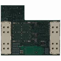
Description
REPLACEMENT POD FOR ICE40,ICE50
Manufacturer
Atmel
Datasheet
1.ATICE50MEM.pdf
(73 pages)
Specifications of ATICE50POD
Accessory Type
POD Replacement Kit
For Use With/related Products
AVR ICE40 and ICE50
Lead Free Status / RoHS Status
Contains lead / RoHS non-compliant


2523A–AVR–11/02
General Description
3.3
3.3.1
3.3.2
3-4
POD Bay
Removing POD from
POD Bay
Inserting POD Into
POD Bay
The ICE50 has a very flexible architecture that will ensure a long product life. The differ-
ent AVR devices are characterised through their number of I/O pins and analog
features. Both the I/O pins and the analog features are implemented on the POD board.
If new AVR devices are made available to the market that contain I/O or analog features
that cannot be emulated by the current POD, Atmel is dedicated to create new POD
modules that support the functionality of the new devices.
If for some reason the POD must be removed from the POD Bay, the recommended
procedure is as described below. See also Figure 3-4.
1. Lift the POD on the front edge until a click is heard. The POD is now ready to be
2. Lift the POD out of the Bay.
Figure 3-4. Removing POD from POD Bay
Without the POD connected, the ICE50 will still be able to emulate core functions of the
AVR (e.g., timers). This feature can be useful in some debugging sessions. If the POD is
inserted and there is no target power applied, the ICE will be held in Reset until target
power is turned on. By disabling POR and BOD Reset in ICE50 other options dialog,
ICE50 will emulate correctly even if target power is not connected.
Only original ICE50 Pods should be used with ICE50 and care should be taken when
placing or removing the POD. During normal use there is no need to remove the POD
from the bay. If for some reason the POD is disconnected, the recommended procedure
to re-insert the POD is as follows. See also Figure 3-5.
1. Place the POD in the ICE50 POD connector. Make sure that the connector male
2. Use both hands and apply pressure on the upper half of the POD (on top of the
3. After pressing the connector firmly in place, use one hand to apply pressure on
pulled up from the bay.
and female guides align.
connector).
the lower half of the POD. You will hear a click when the POD locks into position.
ICE50 User Guide
Related parts for ATICE50POD
Image
Part Number
Description
Manufacturer
Datasheet
Request
R

Part Number:
Description:
EMULATOR IN CIRCUIT MEGAAVR
Manufacturer:
Atmel
Datasheet:

Part Number:
Description:
DEV KIT FOR AVR/AVR32
Manufacturer:
Atmel
Datasheet:

Part Number:
Description:
INTERVAL AND WIPE/WASH WIPER CONTROL IC WITH DELAY
Manufacturer:
ATMEL Corporation
Datasheet:
Part Number:
Description:
Low-Voltage Voice-Switched IC for Hands-Free Operation
Manufacturer:
ATMEL Corporation
Datasheet:
Part Number:
Description:
MONOLITHIC INTEGRATED FEATUREPHONE CIRCUIT
Manufacturer:
ATMEL Corporation
Datasheet:
Part Number:
Description:
AM-FM Receiver IC U4255BM-M
Manufacturer:
ATMEL Corporation
Datasheet:
Part Number:
Description:
Monolithic Integrated Feature Phone Circuit
Manufacturer:
ATMEL Corporation
Datasheet:
Part Number:
Description:
Multistandard Video-IF and Quasi Parallel Sound Processing
Manufacturer:
ATMEL Corporation
Datasheet:
Part Number:
Description:
High-performance EE PLD
Manufacturer:
ATMEL Corporation
Datasheet:
Part Number:
Description:
8-bit Flash Microcontroller
Manufacturer:
ATMEL Corporation
Datasheet:
Part Number:
Description:
2-Wire Serial EEPROM
Manufacturer:
ATMEL Corporation
Datasheet: