ATICE50POD Atmel, ATICE50POD Datasheet - Page 32
ATICE50POD
Manufacturer Part Number
ATICE50POD
Description
REPLACEMENT POD FOR ICE40,ICE50
Manufacturer
Atmel
Datasheet
1.ATICE50MEM.pdf
(73 pages)
Specifications of ATICE50POD
Accessory Type
POD Replacement Kit
For Use With/related Products
AVR ICE40 and ICE50
Lead Free Status / RoHS Status
Contains lead / RoHS non-compliant


2523A–AVR–11/02
General Description
3.7.1.1
3.7.1.2
3.7.2
3.7.3
3-18
Available Clock
Options
ICE50 Probe version
A9902.3.1200.E
External Clock
Signal
Internal Clock Signal
Provided by AVR
Studio
Figure 3-25. External Clock
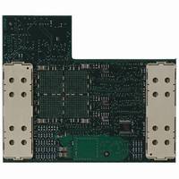
The current version of the Probe has some restrictions with regards to clock options
support. The unsupported clock modes are quite easy to emulate with simple
workarounds as described in Section 3.7.6 and Section 3.7.7. The Probe version can be
found on top of the back side of the Probe (left side of the right picture above).
Version A9902.3.1200.E of the Probe supports the following clock options:
The following clock options are not supported by Probe version A9902.3.1200.C. A
description for workarounds for the unsupported clock modes can be found in section
“External Crystal and External Resonator” on page 19 and “External RC Oscillator” on
page 19.
An external clock signal can be applied to the XTAL1 pin on the emulator probe. The
Emulator can then be set up to use this signal as the system clock. See device selection
for a description of how to set up AVR Studio for this option. The clock signal must meet
the conditions as shown in Table 3-7.
Table 3-7. Clock Signal Conditions
The Emulator may be set up to run on an internal programmable clock. The frequency
range of this programmable clock is 5 kHz to 20 MHz. However, the maximum fre-
quency cannot be set higher than the speed limit of the actual part. Only certain output
frequencies are possible to generate with highest accuracy. However the clock genera-
tor generally produces an output frequency within 0.1% of the desired output frequency.
If the target application should run on the same clock as the AVR chip/emulator, the
internal programmable clock may be driven out on the XTAL2 pin. See section device
selection for a description of how to set up the internal programmable clock.
Frequency
Duty cycle
Absolute maximum input voltage
Recommended input voltage
Minimum high level input voltage
Maximum low level input voltage
External Clock Signal
Internal Clock Signal provided by AVR Studio
External 32 kHz RTC Crystal
Internal Calibrated RC Oscillator
Enable
Enable
XTAL1
XTAL2
5KHz to 20MHz
1.8 - 7.0V
1.8 - 5.5V
Value
ICE50 User Guide
1.7V
50%
0.5V
Related parts for ATICE50POD
Image
Part Number
Description
Manufacturer
Datasheet
Request
R

Part Number:
Description:
EMULATOR IN CIRCUIT MEGAAVR
Manufacturer:
Atmel
Datasheet:

Part Number:
Description:
DEV KIT FOR AVR/AVR32
Manufacturer:
Atmel
Datasheet:

Part Number:
Description:
INTERVAL AND WIPE/WASH WIPER CONTROL IC WITH DELAY
Manufacturer:
ATMEL Corporation
Datasheet:
Part Number:
Description:
Low-Voltage Voice-Switched IC for Hands-Free Operation
Manufacturer:
ATMEL Corporation
Datasheet:
Part Number:
Description:
MONOLITHIC INTEGRATED FEATUREPHONE CIRCUIT
Manufacturer:
ATMEL Corporation
Datasheet:
Part Number:
Description:
AM-FM Receiver IC U4255BM-M
Manufacturer:
ATMEL Corporation
Datasheet:
Part Number:
Description:
Monolithic Integrated Feature Phone Circuit
Manufacturer:
ATMEL Corporation
Datasheet:
Part Number:
Description:
Multistandard Video-IF and Quasi Parallel Sound Processing
Manufacturer:
ATMEL Corporation
Datasheet:
Part Number:
Description:
High-performance EE PLD
Manufacturer:
ATMEL Corporation
Datasheet:
Part Number:
Description:
8-bit Flash Microcontroller
Manufacturer:
ATMEL Corporation
Datasheet:
Part Number:
Description:
2-Wire Serial EEPROM
Manufacturer:
ATMEL Corporation
Datasheet: