ATICE50POD Atmel, ATICE50POD Datasheet - Page 38
ATICE50POD
Manufacturer Part Number
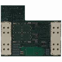
ATICE50POD
Description
REPLACEMENT POD FOR ICE40,ICE50
Manufacturer
Atmel
Datasheet
1.ATICE50MEM.pdf
(73 pages)
Specifications of ATICE50POD
Accessory Type
POD Replacement Kit
For Use With/related Products
AVR ICE40 and ICE50
Lead Free Status / RoHS Status
Contains lead / RoHS non-compliant


2523A–AVR–11/02
Connecting ICE50
4.4
4-4
ICE50 Power-up
Sequence
Warning!
Connecting or disconnecting the POD or Personality Adapter while the target application
is powered might damage the Probe and/or the POD.
Once the Probe and Personality Adapter are connected, continue by correct Power-up
sequence.
When the ICE50 is properly connected to the target and the host PC, the power can be
turned on. The following procedure is recommended to ensure proper communication
between the ICE50 and AVR Studio.
Note:
Once the power-up sequence is done, the next step is to start up and configure AVR
Studio. For more information on Power Supply requirements follow this link.
Power up ICE50, wait for yellow LED to be lit.
Power up target board.
Start AVR Studio.
Every design precaution is taken so that the probe and ICE50 POD should not be
damaged if incorrectly placed. However, selecting wrong adapter, or placing the
adapter with wrong orientation may damage the ICE50 POD.
The equipment will not be harmed in any way if a different power up sequence
is used, but since AVR Studio tries to detect peripherals when started, the
ICE50 will not be detected if not powered.
ICE50 User Guide
Related parts for ATICE50POD
Image
Part Number
Description
Manufacturer
Datasheet
Request
R

Part Number:
Description:
EMULATOR IN CIRCUIT MEGAAVR
Manufacturer:
Atmel
Datasheet:

Part Number:
Description:
DEV KIT FOR AVR/AVR32
Manufacturer:
Atmel
Datasheet:

Part Number:
Description:
INTERVAL AND WIPE/WASH WIPER CONTROL IC WITH DELAY
Manufacturer:
ATMEL Corporation
Datasheet:
Part Number:
Description:
Low-Voltage Voice-Switched IC for Hands-Free Operation
Manufacturer:
ATMEL Corporation
Datasheet:
Part Number:
Description:
MONOLITHIC INTEGRATED FEATUREPHONE CIRCUIT
Manufacturer:
ATMEL Corporation
Datasheet:
Part Number:
Description:
AM-FM Receiver IC U4255BM-M
Manufacturer:
ATMEL Corporation
Datasheet:
Part Number:
Description:
Monolithic Integrated Feature Phone Circuit
Manufacturer:
ATMEL Corporation
Datasheet:
Part Number:
Description:
Multistandard Video-IF and Quasi Parallel Sound Processing
Manufacturer:
ATMEL Corporation
Datasheet:
Part Number:
Description:
High-performance EE PLD
Manufacturer:
ATMEL Corporation
Datasheet:
Part Number:
Description:
8-bit Flash Microcontroller
Manufacturer:
ATMEL Corporation
Datasheet:
Part Number:
Description:
2-Wire Serial EEPROM
Manufacturer:
ATMEL Corporation
Datasheet: