28029 Parallax Inc, 28029 Datasheet
28029
Specifications of 28029


Related parts for 28029


28029 Summary of contents
Page 1
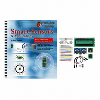
Smart Sensors and Applications Student Guide VERSION 1.0 ...
Page 2
... Parallax, Inc. HomeWork Board, Propeller, Ping))) Parallax, and the Parallax logo are trademarks of Parallax Inc. If you decide to use trademarks of Parallax Inc. on your web page or in printed material, you must state that "(trademark (registered) trademark of Parallax Inc.” upon the first appearance of the trademark name in each printed document or web page ...
Page 3
We maintain active web-based discussion forums for people interested in Parallax products. These lists are accessible from www.parallax.com: • Propeller chip – This list is specifically for our customers using Propeller chips and products. • BASIC Stamp – This list ...
Page 4
...
Page 5
Preface........................................................................................................................iii Introduction and Author's Note ...................................................................................... iii Overview......................................................................................................................... v Before you Start.............................................................................................................. v The Stamps In Class Educational Series ...................................................................... vi Foreign Translations ..................................................................................................... vii Special Contributors ..................................................................................................... vii Chapter 1: The Parallax Serial LCD Display ............................................................1 LCDs in Products............................................................................................................2 ...
Page 6
Page ii · Smart Sensors and Applications Activity #3: Testing the Calibration ............................................................................. 138 Activity #4: Improve Compass Measurements by Averaging ..................................... 143 Activity #5: Mobile Measurements.............................................................................. 148 Summary .................................................................................................................... 159 Chapter 5: Accelerometer Gaming Basics .......................................................... 167 Activity #1: ...
Page 7
Preface INTRODUCTION AND AUTHOR'S NOTE The first time I saw the term "smart sensor" was in Tracy Allen's Applied Sensors text (then known as Earth Measurements). Tracy aptly applied this term to the DS1620 digital thermometer, which has built-in electronics ...
Page 8
Page iv · Smart Sensors and Applications put together such an awesome group of components into a single kit, I'd have to say it was worth the wait. In keeping with the rest of the Stamps in Class tutorials, this ...
Page 9
OVERVIEW The smart sensors kit contains four devices that, when used with the BASIC Stamp and Board of Education or HomeWork Board, can be building blocks for a variety of inventions and student projects. Here is a list of the ...
Page 10
... Control”, Student Guide, Version 1.0, Parallax Inc., 2006 “Applied Sensors”, Student Guide, Version 1.3, Parallax Inc., 2003 “Basic Analog and Digital”, Student Guide, Version 1.3, Parallax Inc., 2004 “Understanding Signals”, Student Guide, Version 1.0, Parallax Inc., 2003 ...
Page 11
... Aristides Alvarez, Technical Illustrator Rich Allred, Graphic Designer Larissa Crittenden, Technical Reviewer Kris Magri, and Technical Editor Stephanie Lindsay. In addition, thanks go to customer Steve Nicholson for test-driving most of the activities. As always, special thanks go to Ken Gracey, the founder of Parallax Inc.’s Stamps in Class educational program. Preface · Page vii ...
Page 12
...
Page 13
Chapter 1: The Parallax Serial LCD Display Displaying the information a sensor sends in a readable format has many uses, and in some applications, it's all that matters. The digital thermometer is a common example that can be found in ...
Page 14
Page 2 · Smart Sensors and Applications LCDS IN PRODUCTS The products shown in Figure 1-2 all have liquid crystal displays. They are easy to read, and the smaller ones consume very little power. Think about how many products you ...
Page 15
It's also a handy tool for testing circuits, sensors, and more. The Debug Terminal has one drawback, and that's the serial cable connection. Consider how many times it wasn't convenient to have your ...
Page 16
Page 4 · Smart Sensors and Applications ACTIVITY #1: CONNECTING AND TESTING THE LCD Along with the electrical connections and some simple PBASIC test programs for the Parallax Serial LCD, this activity introduces the how is just a special case ...
Page 17
Disconnect power from your Board of Education. √ Connect the Board of Education's Vss socket to the LCD's GND pin. √ Connect the Board of Education's P14 socket to the LCD's RX pin, as shown in Figure 1-4. √ ...
Page 18
Page 6 · Smart Sensors and Applications Testing the Serial LCD The Parallax Serial LCD has a self-test mode you can use to make sure it's in working order and that the contrast is properly set. Figure 1-5 shows the ...
Page 19
If the display seems dim or looks blank, there is a contrast adjustment potentiometer shown in Figure 1-7 that you can turn with a screwdriver. If the display is already clear and all the characters look good, you probably ...
Page 20
Figure 1-9 shows the mode table printed on the back of the Parallax Serial LCD. If you want to send messages at other baud rates, (2400 or 19,200 bps), use this table and adjust SW1 and SW2 accordingly. ACTIVITY #2: ...
Page 21
The minimal version of the SEROUT SEROUT Pin, BaudMode, [ DataItem, {DataItem, ...} ] In our programs, the argument has since the LCD's RX (receive data) pin is Pin connected to BASIC Stamp I/O pin P14. The ...
Page 22
Page 10 · Smart Sensors and Applications activate its display. Here's the PBASIC command for sending the serial LCD the value 22: SEROUT 14, 84, [22] Used in this way example of an LCD control code. Here's a ...
Page 23
Smart Sensors and Applications - LcdTestMessage.bs2 ' Display a test message on the Parallax Serial LCD. ' {$STAMP BS2} ' {$PBASIC 2.5} SEROUT 14, 84, [22, 12] PAUSE 5 SEROUT 14, 84, ["See this?", 13, "The LCD works!"] END ...
Page 24
Page 12 · Smart Sensors and Applications Display Numbers with Formatters Most of the formatters that worked for displaying numbers with the Debug Terminal can also be used with the Parallax Serial LCD. The useful, but you can also use ...
Page 25
Your Turn - Other Formatters √ Try replacing with DEC DEC2 √ Repeat with the formatter. ? √ If necessary, look these commands up in either the BASIC Stamp Manual or the BASIC Stamp Editor's Help. Also try them in ...
Page 26
Page 14 · Smart Sensors and Applications The values from to and 128 143 where each value places the cursor. You can use values from cursor at characters the top line of the LCD (Line 0). ...
Page 27
Here's a code block that will make the text "Line 1" slide across the display's bottom line, from right to left. FOR index = IMPORTANT: Leave a space after the 1 in "Line 1 " SEROUT ...
Page 28
Page 16 · Smart Sensors and Applications ' Shift "Line 1" across Line 1 right to left, then left to right. FOR index = IMPORTANT: Make sure there's a space after the 1 in "Line 1 ...
Page 29
ACTIVITY #3: TIMER APPLICATION This activity applies the techniques introduced in Activity # hour-minute-second timer. Displaying Time Elapsed Here is a code block that starts the LCD, clears the screen, and places some display characters on the LCD ...
Page 30
Page 18 · Smart Sensors and Applications √ Verify that the display works as advertised. ' Smart Sensors and Applications - LcdTimer.bs2 ' Display elapsed time with BS2 and Parallax Serial LCD. ' {$STAMP BS2} ' {$PBASIC 2.5} hours VAR ...
Page 31
LcdCr CON LcdOff CON LcdOn CON Line0 CON Line1 CON These declarations will make your code easier to understand, which is especially important if you decide to make changes to your program after not having looked at it for several ...
Page 32
Page 20 · Smart Sensors and Applications Figure 1-13: Predefined Custom Characters O (Backslash) and 1 (Tilde) Example Program: PredfinedCustomCharacters.bs2 This example sends the serial LCD the two commands to make it display Custom Characters 0 and 1, the backslash ...
Page 33
Figure 1-14: Custom Character Define Commands After sending the code that tells the LCD which custom character you are about to define, you have to then send eight bytes that describe the character. The LCD uses the lowest five bits ...
Page 34
Page 22 · Smart Sensors and Applications Custom Character 7. It also uses a technique for drawing the characters with asterisks in the comments to the right of the SEROUT all the binary values set to %00000, and then draw ...
Page 35
DO SEROUT 14, 84, [133] SEROUT 14, 84, [0] PAUSE 1250 SEROUT 14, 84, [8] SEROUT 14, 84, [7] PAUSE 1500 LOOP Example Program: Hourglass.bs2 This program defines and displays the hourglass custom characters just discussed. √ Enter, save, and ...
Page 36
Page 24 · Smart Sensors and Applications SEROUT 14, 84, [22, 12] PAUSE 5 ' -----[ Main Routine ]------------------------------------------------------- DO SEROUT 14, 84, [133] SEROUT 14, 84, [0] PAUSE 1250 SEROUT 14, 84, [8] SEROUT 14, 84, [7] PAUSE 1500 ...
Page 37
Backspace, Custom Character 1, backspace, Custom Character 2, etc. ' optional Pace argument of 100 sends each value every 1/ second. SEROUT 14, 84, 100, [ ...
Page 38
Page 26 · Smart Sensors and Applications message is larger than the display window, stopping at the left edge of the display will keep the rest of the message from becoming visible. To get text to scroll across just one ...
Page 39
The next example program also has variables you can set to configure different window locations, widths, and increments. After setting these variable values, you can then call the subroutine, and it does the rest of the work. Here is an ...
Page 40
Page 28 · Smart Sensors and Applications Example Program - TestScrollingSubroutine.bs2 √ Review the code blocks in the Main Routine of the program and predict how wide the scrolling window will be, what text will be displayed, and how many ...
Page 41
Configuration variables for Scroll_Message subroutine. increment VAR Nib windowRight VAR Byte windowLeft VAR Byte messageStart VAR Byte messageEnd VAR Byte ' -----[ Initialization ]----------------------------------------------------- SEROUT LcdPin, T9600, [LcdOn, LcdCls] PAUSE 5 ' -----[ Main Routine ]------------------------------------------------------- ' Set values ...
Page 42
Page 30 · Smart Sensors and Applications SEROUT LcdPin, T9600, [" "] NEXT PAUSE timeOff SEROUT LcdPin, T9600, [cursorStart] ' This FOR...NEXT loop refreshes the message, shifted increment characters ' to the left each time through until the end of ...
Page 43
Figure 1-19 shows the setup and Step four-character wide window. In the setup step, nothing is displayed in the window. Then, Step 0 places the cursor in position 137, and displays character 0, the "M". Figure 1-19: ...
Page 44
Page 32 · Smart Sensors and Applications √ Figure 1-21 shows Steps 3 and 4. Moving the cursor to position 134 and displaying characters "Mess" is still the same sequence, but when the "M" leaves the window, ...
Page 45
The TestScrollingSubroutine.bs2 uses the variables shown in Figure 1-23 for the sliding window. The variable stores the position that the cursor is placed each cursorStart time before it starts printing the characters in the message. In the figure, stores the ...
Page 46
Page 34 · Smart Sensors and Applications SUMMARY The liquid crystal display (LCD) is used in a tremendous variety of products. Simple character displays like the Parallax 2X16 serial LCD can substitute for the Debug Terminal's display features, which is ...
Page 47
This chapter also introduced a subroutine for scrolling text from right to left inside a window. This subroutine looks for start and stop addresses that correspond to Symbol address labels that precede the DATA way the subroutine's text is displayed ...
Page 48
Page 36 · Smart Sensors and Applications 5. Write a command to send the LCD messages when SW1 and SW2 are SEROUT both ON. 6. Write a command to send the LCD a message when SW1 is ON and SEROUT ...
Page 49
Solutions Q1. Wrist watch, calculator, telephone (answers will vary). Q2. Two rows of text, each row is 16 characters wide. Q3. The command. SEROUT Q4. When using the command you must specify the pin number and the baud SEROUT rate. ...
Page 50
Page 38 · Smart Sensors and Applications E3. Example solution: ' Smart Sensors and Applications - Ch1_Ex03.bs2 ' Make message flash on and off once per second ' {$STAMP BS2} ' {$PBASIC 2.5} SEROUT 14, 84, [22, 12] ' 1234567890123456 ...
Page 51
P1. Example solution: ' Smart Sensors and Applications - Ch1_Project1.bs2 ' Display a 6-line message ' {$STAMP BS2} ' {$PBASIC 2.5} LcdPin PIN 14 T9600 CON 84 PAUSE 250 SEROUT 14, 84, [22, 12] PAUSE 5 SEROUT LcdPin, T9600, ["I ...
Page 52
Page 40 · Smart Sensors and Applications FOR copies = SEROUT 14, 84, [0] NEXT PAUSE 1000 SEROUT 14, 84, [Line1, "now re-defining"]' Display message on Line 1 PAUSE 1000 SEROUT 14, 84, [Line1, " SEROUT 14, ...
Page 53
Chapter 2: The Ping))) Ultrasonic Distance Sensor The Ping))) sensor interfaced with a BASIC Stamp can measure how far away objects are. With a range of 3 centimeters to 3.3 meters, it's a shoo-in for any number of robotics and ...
Page 54
Page 42 · Smart Sensors and Applications The BASIC Stamp command uses a variable to store how long the high signal PULSIN from the Ping))) sensor lasted. This time measurement is how long it took sound to travel to the ...
Page 55
Figure 2-3: Ping))) Sensor Schematic and Wiring Diagram Testing the Ping))) Sensor As mentioned earlier, the Ping))) sensor needs a start pulse from the BASIC Stamp to start its measurement. A pulse to P15 that lasts 10 µs ( detected ...
Page 56
Page 44 · Smart Sensors and Applications √ Move the target to a distance from the Ping))) sensor and verify that the value of the time variable roughly doubled. √ Point your Ping))) sensor at a variety ...
Page 57
... In addition, as Ken Gracey of Parallax Inc. discovered during a classroom demonstration at his son’s school, some objects with soft, irregular surfaces (such as stuffed animals) will absorb rather than reflect sound and therefore can be difficult for the Ping))) sensor to detect. Objects with smooth surfaces that readily reflect sound are easier for the sensor to detect. √ ...
Page 58
Page 46 · Smart Sensors and Applications ACTIVITY #2: CENTIMETER MEASUREMENTS This activity demonstrates how to use the speed of sound and the PBASIC Multiply High operator ( ) to calculate the distance of an object based on the echo ...
Page 59
The speed of sound in air at room temperature 72 °F (22.2 °C) is 344.8 m/s. Dividing 10,000 into this leaves us with S object-cm 344.8 t PULSIN S = object- cm 10,000 0.03448 t = PULSIN The BASIC Stamp ...
Page 60
Page 48 · Smart Sensors and Applications Example Program: PingMeasureCm.bs2 √ Enter, save and run PingMeasureCm.bs2. √ Move the target object until the measurement displays 20 cm. √ Align your ruler with that measurement. somewhere with the Ping))) sensor, typically ...
Page 61
ACTIVITY #3: INCH MEASUREMENTS Most electronic distance measuring devices offer results in either metric or English units. For example, the calipers shown in Figure 2-6 has a button you can press to choose between mm and inches. Other measuring devices ...
Page 62
Page 50 · Smart Sensors and Applications Example Program: PingMeasureCmAndIn.bs2 √ Enter, save, and run PingMeasureCmAndIn.bs2. √ Experiment with the distance measurements and verify that they are correct in both systems. ' Smart Sensors and Applications - PingMeasureCmAndIn.bs2 ' Measure ...
Page 63
ACTIVITY #4: MOBILE MEASUREMENTS This activity demonstrates displaying the Ping))) sensor's centimeter and inch measurements on the Parallax Serial LCD. Provided you're using a battery, you can disconnect from your computer and take the setup to remote locations of your ...
Page 64
Page 52 · Smart Sensors and Applications Board of Education Rev C and USB Board of Education Cable Connections These instructions are for the boards that have servo ports with a Vdd/Vss jumper in between, such as the Board of ...
Page 65
Vdd vs. Vin jumper settings determine which power supply is connected to the X4 and X5 ports. When the jumper is set to Vdd, these ports receive regulated 5 V from the Board of Education's voltage regulator. If the jumper ...
Page 66
Page 54 · Smart Sensors and Applications √ Connect the other end of the cable so that the black wire is connected to the Ping))) module's GND pin, the red wire is connected to the 5 V pin, and the ...
Page 67
Plug the Parallax Serial LCD into the breadboard as shown in Figure 2-11 on page 56. √ Plug one end of the extension cable into the 3-pin header, making sure the white, red, and black wires are oriented as ...
Page 68
Page 56 · Smart Sensors and Applications Figure 2-11: Breadboard Connections for Ping))) Sensor and Parallax Serial LCD ...
Page 69
LCD Distance Display It doesn't take much in the way of changes to modify PingMeasureCmAndIn.bs2 to make it display its measurements on the LCD. First, an Initialization section has to be added so that the program waits for the power ...
Page 70
Page 58 · Smart Sensors and Applications inDistance VAR Word time VAR Word PAUSE 200 SEROUT 14, 84, [22, 12] PAUSE 5 DEBUG CLS, "Program running..." DO PULSOUT 15, 5 PULSIN 15, 1, time cmDistance = cmConstant ** time inDistance ...
Page 71
Air temperature, on the other hand, can cause measurable distance errors. The speed of sound increases by 0.6 meters per second (m/s) for every degree- Celsius (°C) increase in temperature. Since the speed of sound is about 331.5 ...
Page 72
Page 60 · Smart Sensors and Applications move the object half a centimeter beyond 100 cm before it would transition from 99 to 100 cm. 346.5 344 error = 344.8 0.49% = Your Turn - Room Temperature Vs. ...
Page 73
SUMMARY The BASIC Stamp requests a measurement from the Ping))) sensor by sending it a brief pulse, which causes it to emit a 40 kHz chirp. Then, the Ping))) listens for an echo of that chirp. It reports the echo ...
Page 74
Page 62 · Smart Sensors and Applications Exercises 1. Calculate how many meters away an object is if the echo time is 15 ms, and the temperature is 22.5 °C. 2. Calculate the °C equivalent of 100 °F. 3. Calculate ...
Page 75
Solutions Q1. 3 centimeters to 3.3 meters. Q2. Sound with frequencies above 20 kHz. Q3. A high pulse, whose duration corresponds to the time it took for the chirp sound to travel to the object and back. Q4. a) Distance ...
Page 76
Page 64 · Smart Sensors and Applications PULSIN 15, 1, time cmDistance = cmConstant ** time SEROUT LCD, 84, [128, DEC3 cmDistance, " cm"] IF cmDistance >= MaxDistance THEN HIGH LED PAUSE 100 LOOP P2. Example solution: ' Smart Sensors ...
Page 77
Chapter 3: The Memsic Dual-Axis Accelerometer Acceleration is a measure of how quickly speed changes. Just as a speedometer is a meter that measures speed, an accelerometer is a meter that measures acceleration. You can use an accelerometer's ability to ...
Page 78
Page 66 · Smart Sensors and Applications The accelerometer you will be working with in this text is the Parallax Memsic 2125 Dual Axis Accelerometer module shown in Figure 3-1. This module measures less than ” ...
Page 79
THE MX2125 ACCELEROMETER – HOW IT WORKS The MX2125’s design is amazingly simple. It has a chamber of gas with a heating element in the center and four temperature sensors around its edge. Just as hot air rises and cooler ...
Page 80
ACTIVITY #1: CONNECTING AND TILT-TESTING THE MX2125 In this activity, you will connect the accelerometer module to the BASIC Stamp, run a test program, and verify that it can be used to sense tilt. Parts Required (2) 3-inch Jumper Wires ...
Page 81
Figure 3-4: Accelerometer Axis Pulse Measurements For room temperature testing, you can get a pretty good indication of tilt by just measuring the high times of the pulses sent by the MX2125’s Xout and Yout pins with the command. Depending ...
Page 82
Page 70 · Smart Sensors and Applications √ Make sure your board is sitting flat on the table, oriented with its x and y axes as shown in Figure 3-4. √ Enter and run SimpleTilt.bs2. ' Smart Sensors and Applications ...
Page 83
Grab the edge of the board with the Y-Axis label and gradually lift it toward you. The value should increase as you increase the tilt. y √ Keep tilting the board toward you until it's straight up and down. ...
Page 84
Page 72 · Smart Sensors and Applications Building the Accelerometer and LCD Circuits The schematics shown in Figure 3-6 are identical to the ones that have been used for the Memsic accelerometer and Parallax Serial LCD in previous activities. The ...
Page 85
Then insert the Parallax Serial LCD as shown Figure 3-8. Figure 3-8: Debug Terminal Output LCD Tilt Display Modifying any of the accelerometer example programs from this chapter to make them display measurements on the LCD is typically a ...
Page 86
Page 74 · Smart Sensors and Applications Always remember to add this initialization, either before the Main Routine small programs, before the first keyword. That will keep the initialization from being DO repeated over and over again in ...
Page 87
DEBUG CLS ' Initialize LCD PAUSE 200 SEROUT 14, 84, [22, 12] PAUSE 5 DO PULSIN PULSIN DEBUG HOME, DEC4 ? X, DEC4 ? Y SEROUT 14, 84, [128, DEC4 ? X, ...
Page 88
Page 76 · Smart Sensors and Applications ACTIVITY #3: SCALING DOWN AND OFFSETTING INPUT VALUES When working with the MX2125 and BASIC Stamp 2, tilt measurements range between 1875 and 3125. This range may have to be scaled and offset ...
Page 89
Figure 3-10 shows how to apply these steps with a single PBASIC command that performs both scaling and offset. Keep in mind that PBASIC calculations work from left to right unless they are overridden with parentheses. So the first thing ...
Page 90
Page 78 · Smart Sensors and Applications Always round your ScaleConstant result down, even if the result is already an integer! Otherwise, the largest value in your input scale might be one value outside the output scale's range. Clamping the ...
Page 91
DEBUGIN DEC value value = (value MIN 1875 MAX 3125) - 1875 ** 13369 - 127 DEBUG "scaled to ", SDEC value, CR LOOP Figure 3-11: Scaling Test √ Click in the Debug Terminal's Transmit windowpane and enter this sequence, ...
Page 92
Page 80 · Smart Sensors and Applications √ Test various other values that range from 1875 to 3125, and verify with a calculator that the output value’s position in the output range is proportional to the input value’s position in ...
Page 93
Figure 3-12: Two’s Complement Signed Decimal Number Line (DEC 1)0000000000000001 -32768...............-1...0...1...............32767 | | | 1000000000000000 (DEC 32768) The pattern emerges when you can see an unsigned decimal number compared next to its signed decimal and binary equivalents. √ Try running ...
Page 94
Page 82 · Smart Sensors and Applications Your Turn - A Closer Look at the ScaleConstant and ** Operator For small input and output ranges, we can examine them with a calculator, pencil and paper. Let's take ...
Page 95
Table 3-2: Measured voltages during charge cycle Value **Scale Constant 0 x 0.2999 = 1 x 0.2999 = 2 x 0.2999 = 3 x 0.2999 = 4 x 0.2999 = 5 x 0.2999 = 6 x 0.2999 = 7 x ...
Page 96
Page 84 · Smart Sensors and Applications Figure 3-13: Scaling and Offset for 1/100 g. Your Turn - Developing the Program The goal here is to use the scaling techniques from Activity #3 to modify the program from Activity #1 ...
Page 97
Open SimpleTilt.bs2 from Activity #1 and save it as CentigravityTilt.bs2 √ Follow the steps for scaling from Activity #3 and determine the scale constants. √ Add lines of code to the program that scale the x and y values ...
Page 98
Page 86 · Smart Sensors and Applications The arctangent function can be used to determine the accelerometer's rotation angle with its x and y measurements. PBASIC has an operator called −1 calculating tan (y/x). To calculate the arctangent of y/x ...
Page 99
Converting from Brads to Degrees with In the previous activity, we used the to a smaller range. Converting from brads to degrees involves scaling a smaller scale 255 to a larger scale 359. The ...
Page 100
Page 88 · Smart Sensors and Applications This demonstrates that if the angle variable stores a measure of brads, and you want to store a measure of degrees instead, use this command: angle = 361 */ angle Most documents recommend ...
Page 101
To calculate x and y values to enter into the Debug Terminal, use these equations sin = x h cosθ = For example, let's say that h = 127 and θ = 45°, then the x and y ...
Page 102
Page 90 · Smart Sensors and Applications Some values will be lower than you predict. For example, when h = 100 and θ = 30° and x = 87. The Debug Terminal will display 21 for the ...
Page 103
VAR Word brads VAR Word DEBUG CLS, "brads */ 360 */ 361", CR FOR brads = 0 TO 255 DEBUG DEC3 brads angle = brads */ 360 DEBUG " ", DEC3 angle angle = brads */ 361 DEBUG " ...
Page 104
Page 92 · Smart Sensors and Applications Measuring Tilt Angle On the Vertical Plane The angle of your board's clockwise rotation in the vertical plane (θ) is the arctangent of the gravity's effect on the MX2125's y-axis (A shown in ...
Page 105
Figure 3-22: Accelerometer Rotated 30° Clockwise ⎛ ⎞ 1 ⎜ ⎟ 2 ⎜ ⎟ 1 tan − ° ⎜ ...
Page 106
Page 94 · Smart Sensors and Applications The General Case The angle of rotation (θ) is the inverse tangent or arctangent of the component of gravity acting on the Memsic 2125’s Y sensing (A ). The figure below shows the ...
Page 107
Enter, save, and run VertWheelRotation.bs2. √ Hold the board in vertically in front of you like a steering wheel. √ Rotate the board clockwise, and watch the angle measurement grow. √ Verify that the display angle ranges from 0 ...
Page 108
Page 96 · Smart Sensors and Applications flicker that results is not pleasant to examine for any length of time. right of the cursor on a given line. While it still causes a little bit of flicker in each value, ...
Page 109
Custom Character Definitions Remember, 248 defines Custom Character 0. 249 defines Custom Character 1. 250 defines Custom Character 2, and so on 255, which defines Custom Character 7. The command that the DEBUG SEROUT Debug Terminal. The SEROUT ...
Page 110
Page 98 · Smart Sensors and Applications To reverse the angle of rotation the that program displays, all you have use −Ay instead Take a look at Figure 3-25 −1/2, and the ...
Page 111
Figure 3-26: Tilt Axes on the Board of Education Sine and Cosine Figure 3-27 shows the relationship between the sides of a right triangle and the sine and cosine functions. The sine of an angle is the opposite side of ...
Page 112
Page 100 · Smart Sensors and Applications Note from the equations for Figure 3-27 that the x value can be at most the same as h when θ = 0°. Likewise, the y value can be at most h when ...
Page 113
Figure 3-29 shows the BASIC Stamp version of a unit circle for its operators. Instead of results that range from − the results for from −127 to 127. Angles for the instead of 45°, use 32 brads. Instead ...
Page 114
Page 102 · Smart Sensors and Applications sine VAR Word cosine VAR Word DEBUG "Degrees Brads Cosine FOR degrees = 0 TO 359 STEP 15 brads = degrees ** 46733 sine = SIN brads cosine = COS brads DEBUG " ...
Page 115
The next example program uses modified versions of these subroutines. Remember that the and SIN COS divide the result by 127, you'll get a value between −1 and 1 that is an ...
Page 116
Page 104 · Smart Sensors and Applications ' -----[ Constants ]---------------------------------------------------------- Negative CON 1 Positive CON 0 ' -----[ Variables ]---------------------------------------------------------- sine VAR Word side VAR Word angle VAR Word sign VAR Bit ' -----[ Initialization ]----------------------------------------------------- DEBUG CLS sine ...
Page 117
IF (COS angle <= side) THEN EXIT angle = angle + 1 LOOP angle = angle */ 361 IF sign = Negative THEN angle = 180 - angle' Adjust if sign is negative. RETURN Your Turn - Testing the Arccosine ...
Page 118
Page 106 · Smart Sensors and Applications Figure 3-31: Tilting the Board of Education, Tilting the Memsic Accelerometer Figure 3-32 shows how arcsine can be used to determine the tilt angle. Looking at the Memsic Accelerometer Module from the side, ...
Page 119
Figure 3-32: Determining Tilt Angle with Arcsine With the MX2125, a measurement of 1875 is −1 g, and a measurement of 3125 Activity #3, we scaled this to a range of −127 to 127. Remember that ...
Page 120
Page 108 · Smart Sensors and Applications side = x GOSUB Arcsine DEBUG HOME, "x tilt angle = ", CLREOL, SDEC3 angle, CR side = y GOSUB Arcsine DEBUG "y tilt angle = ", CLREOL, SDEC3 angle PAUSE 100 LOOP ...
Page 121
PULSIN Scale and offset x and y-axis values to -127 to 127 MIN 1875 MAX 3125) - 1875 ** 13369 - 127 MIN 1875 MAX 3125) - 1875 ** 13369 ...
Page 122
Page 110 · Smart Sensors and Applications Your Turn - LCD Display Modifying the example program to display the tilt measurements on the Parallax Serial LCD is still a matter of adding an Initialization routine and porting commands. As with ...
Page 123
Your Turn - Adjustments If your display did not go all the way to 90° when you held your board with a particular axis vertical, you can customize your scaling and offset to get it to fit. This will involve ...
Page 124
Page 112 · Smart Sensors and Applications SUMMARY This chapter focused on sensing the acceleration due to gravity with the Memsic 2125 Dual Axis Accelerometer. Sensing gravity makes it possible to measure both tilt and rotation. The Memsic Accelerometer transmits ...
Page 125
MIN 1875 MAX 3125) - 1875 ** 13369 - 127 value 13369 is determined by the Questions 1. What are seven quantities you can measure with an accelerometer? 2. What does MEMS stand for? 3. ...
Page 126
Page 114 · Smart Sensors and Applications Projects 1. Design a device that counts the number of times you rotate your board on the vertical plane. Assume you are starting at 0˚. 2. Design a device that displays an alarm ...
Page 127
Solutions Q1. Acceleration, tilt and tilt angle, incline, rotation, vibration, collision, gravity. Q2. Micro electro-mechanical systems. Q3. A bubble of heated gas. Q4. Yes, either static or dynamic. Q5. Add an initialization routine for the LCD, and convert the commands. ...
Page 128
Page 116 · Smart Sensors and Applications P1. Example solution: ' Smart Sensors and Applications - Ch3Proj1.bs2 ' Based on VertWheelRotation.bs2, this device counts the number ' of times the board has been rotated on the vertical plane. '{$STAMP BS2} ...
Page 129
P2. Example solution: Below is a modified main routine from HorizontalTilt.bs2 ' -----[ Main Routine ]------------------------------------------------------- DO PULSIN PULSIN Scale and offset x and y-axis values to -127 to 127 ...
Page 130
Page 118 · Smart Sensors and Applications ...
Page 131
Chapter 4: The Hitachi HM55B Compass Module The Hitachi HM55B Compass module measures direction. You can use it along with your BASIC Stamp, Board of Education, and Parallax Serial LCD to make a digital compass that works as shown in ...
Page 132
Page 120 · Smart Sensors and Applications trigonometry identities, it turns out that the angle θ is the arctangent of −y/ addition to accelerometer rotation, the compass module's angle from north is another value that can be determined ...
Page 133
Schematic and Wiring Diagram The HM55B can be connected with its Dout and Din pins tied together so that they transmit and receive signals to and from the same BASIC Stamp I/O pin. Another BASIC Stamp I/O pin is connected ...
Page 134
Page 122 · Smart Sensors and Applications Figure 4-4: Debug Terminal Output with Compass Facing 35° Clockwise of North Example Program: TestCompass.bs2 Free Download! This program is available as a free .bs2 file download from the Smart Sensors and Applications ...
Page 135
DinDout PIN 2 Clk PIN 0 En PIN 1 ' -----[ Constants ]---------------------------------------------------------- Reset CON %0000 Measure CON %1000 Report CON %1100 Ready CON %1100 NegMask CON %1111100000000000 ' -----[ Variables ]---------------------------------------------------------- x VAR Word y VAR Word status VAR ...
Page 136
Page 124 · Smart Sensors and Applications SHIFTIN DinDout,clk,MSBPOST,[Status\4] LOOP UNTIL status = Ready SHIFTIN DinDout,clk,MSBPOST,[x\11,y\11] HIGH En IF (y.BIT10 = 1) THEN NegMask IF (x.BIT10 = 1) THEN NegMask RETURN Your ...
Page 137
Find a total magnetic field intensity map that shows your locale, and then use it to calculate the x-axis magnetic field intensity units for your compass module. If the total magnetic field intensity was listed in nanoteslas, then your ...
Page 138
Page 126 · Smart Sensors and Applications Figure 4-5: Bar Magnet’s Field above the Compass Module √ Keep the bar magnet horizontal at the same height, and rotate it so that its N and S poles are no longer aligned ...
Page 139
You can also hold the bar magnet at the same level with the compass module, directly in front of it, as shown in Figure 4-6a. This time the poles magnet's poles are lined up with north and south instead of ...
Page 140
Page 128 · Smart Sensors and Applications module. With a mechanical compass, its bar magnet automatically lines up with north, so you will instead have to move the compass module around the mechanical compass. √ Try it, and note how ...
Page 141
Figure 4-7: Calibration Compass √ Place your copy of Figure 4 flat, level, non metallic surface. Make sure far away from your monitor as your programming cable can reach. The location should also be as ...
Page 142
Page 130 · Smart Sensors and Applications mechanical compass on your work surface. The direction of north it indicates should not change does, find a different location without magnetic interference. √ Use the mechanical compass to align the ...
Page 143
When you run CalibrateCompass.bs2, you will first be prompted to click the Debug Terminal's Transmit windowpane (shown in Figure 4-10), and then to press Enter. After that you will be prompted to type C for calibrate or R for review ...
Page 144
Page 132 · Smart Sensors and Applications Example Program - CalibrateCompass.bs2 Free Download! This program is available as a free .bs2 file download from the Smart Sensors and Applications Product Page at www.parallax.com. If you would like to know how ...
Page 145
VAR Word fraction VAR Nib brads VAR Byte table VAR Byte(2) temp VAR Word(2) axisOffset VAR Word ' -----[ Main Routine ]------------------------------------------------------- DEBUG "Click the Transmit Windowpane, ", CR, ' Wait for user. "then press Enter... ", CR, CR ...
Page 146
Page 134 · Smart Sensors and Applications ' south, then west. It then averages the maximum and minimum values for each ' axis and stores that average in the EEPROM area reserved by the ' CompassOffsets DATA directive. Get_And_Store_Axis_Offsets: ' ...
Page 147
This subroutine prompts the user to point the compass to directions ' separated by 22.5 degrees and stores the angle for each of the measurements ' in the EEPROM area reserved by the CompassCal DATA directive. Get_And_Store_Interpolation: FOR counter ...
Page 148
Page 136 · Smart Sensors and Applications DEBUG CR, "Axis Offsets:", CR READ CompassOffsets, Word x DEBUG CR, "x-Offset = ", SDEC x READ CompassOffsets + 2, Word y DEBUG CR, "y-Offset = ", SDEC y, CR DEBUG CR, "Index ...
Page 149
SHIFTIN DinDout,clk,MSBPOST,[Status\4] LOOP UNTIL status = Ready SHIFTIN DinDout,clk,MSBPOST,[x\11,y\11] HIGH En IF (y.BIT10 = 1) THEN NegMask IF (x.BIT10 = 1) THEN NegMask RETURN ' -----[ Subroutine - Compass_Correct_Offsets ]------------------------------- ' This ...
Page 150
Page 138 · Smart Sensors and Applications ACTIVITY #3: TESTING THE CALIBRATION After Activity #2, the program in this activity should make your compass perform pretty well, well enough to correctly recognize most of the 64 directions in Figure 4-11. ...
Page 151
Heading TestCalibratedCompass.bs2 goes and finds the values that CalibrateCompass.bs2 recorded in the BASIC Stamp's EEPROM memory. Then, it uses the values to correct for scale error, and refines the measurements using a technique called linear interpolation. √ Print or photocopy ...
Page 152
Page 140 · Smart Sensors and Applications ' That calibration process must be performed prior to running ' this test program For instructions on how to perform the calibration process, ' consult Chapter #4, Activity # ...
Page 153
GOSUB Compass_Get_Axes GOSUB Compass_Correct_Offsets angle = x ATN -y DEBUG HOME, "x-axis N(-S) = ",SDEC x, CLREOL, CR, "y-axis W(-E) = ", SDEC y, CLREOL GOSUB Compass_Interpolate DEBUG CR, CR, "angle = ", DEC angle, " brads", CLREOL angle = ...
Page 154
Page 142 · Smart Sensors and Applications ' These EEPROM values were written by CalibrateCompass.bs2. Compass_Correct_Offsets: READ CompassOffsets, Word axisOffset axisOffset READ CompassOffsets + 2, Word axisOffset axisOffset RETURN ' -----[ Subroutine ...
Page 155
ELSE index = index - 1 READ CompassCal + index, table(current) DO table(previous) = table(current) index = index + 1 READ CompassCal + index, table(current) IF ...
Page 156
Page 144 · Smart Sensors and Applications One effective way to eliminate the effects of noise is by taking an average of the compass' x and y axis measurements. That way, if noise causes one measurement little ...
Page 157
Divide xSum sign = xSum.BIT15 xSum = ABS(xSum xSum / 10 IF xSum // 10 >=5 THEN sign = Negative THEN sign = ySum.BIT15 ySum = ABS(ySum) ...
Page 158
Page 146 · Smart Sensors and Applications The procedure for converting a program to average its x and y-axis measurements was applied to TestCompass.bs2, and then saved as TestCompassAveraged.bs2. √ Open and run TestCompass.bs2 from activity #1. √ Watch the ...
Page 159
DO GOSUB Compass_Get_Axes angle = x ATN -y angle = angle */ 361 DEBUG HOME, "x-axis N(-S) = ",SDEC x, CLREOL, CR, "y-axis W(-E) = ", SDEC y, CLREOL, CR, CR, "angle = ", DEC angle, " degrees", CLREOL PAUSE ...
Page 160
Page 148 · Smart Sensors and Applications xSum = ABS(xSum xSum / 10 IF xSum // 10 >=5 THEN sign = Negative THEN sign = ySum.BIT15 ySum = ...
Page 161
Parts Required (1) Hitachi HM55B Compass Module (1) Parallax Serial LCD (2×16) (1) 14-inch LCD Extension Cable (6) Jumper Wires If you are working from a BASIC Stamp HomeWork Board or a serial Board of Education Rev ...
Page 162
Page 150 · Smart Sensors and Applications Board of Education Rev C and USB Board of Education Cable Connections These instructions are for the boards that have servo ports with a Vdd/Vss jumper in between, such as the Board of ...
Page 163
Figure 4-14: Parallax Serial LCD Servo Port Connections √ Plug the power back into the Board of Education. √ Set the Board of Education's 3-position switch to 2. √ Skip to Optional LCD Mounting Brackets on page 153. All other ...
Page 164
Page 152 · Smart Sensors and Applications √ Plug one end of the extension cable into the 3-pin header on the board as shown in Figure 4-16. Make sure the white, red, and black wires are oriented as shown. The ...
Page 165
Figure 4-16: Compass Module and Parallax Serial LCD Connected with Extension Cable √ Double-check all your connections and make sure they are correct. WARNING! Do not reconnect power to your board until you are positive the connections are correct. If ...
Page 166
Page 154 · Smart Sensors and Applications Figure 4-17: Assembling the Optional LCD Bracket Parts Required (4) 90-degree mounting brackets (2) 1/4-inch #4 round nylon spacers (2) 1/2-inch 4-40 pan-head screws (4) 1/4-inch 4-40 pan-head screws (6) 4-40 zinc plated ...
Page 167
LCD Display Programming This LCD initialization routine takes care of the LCD initialization basics, defines Custom Character the ° symbol, then displays static text (text that won't change while the program is running). ' LCD Initialization routine ...
Page 168
Page 156 · Smart Sensors and Applications This example program is a modified version of TestCompass.bs2 that uses LCD display commands instead of Debug Terminal commands. √ Open LcdTestCompass.bs2 try running it with the serial cable disconnected. ' -----[ Title ...
Page 169
SEROUT 14, 84, [129, "Heading...", 149, "x=", 158, "y="] ' -----[ Main Routine ]------------------------------------------------------- DO GOSUB Compass_Get_Axes angle = x ATN -y angle = angle */ 361 ' LCD Display heading in degrees on top line and x and y ...
Page 170
Page 158 · Smart Sensors and Applications Your Turn Try extending the Your Turn from Activity #4 with the Parallax Serial LCD. Don't worry about adding LCD functionality to the calibration program, just to the modified calibration test program from ...
Page 171
SUMMARY The Hitachi HM55B Compass module is a dual-axis magnetic field sensor capable of detecting microtesla variations in the components of the earth's magnetic field acting on its x and y axes. The module's angle from north can be determined ...
Page 172
Page 160 · Smart Sensors and Applications Exercises 1. Calculate the angle from north if the x axis reading is 34 and the y-axis reading Calculate the angle from north if the x-axis reading is 16 and ...
Page 173
Solutions Q1 the value reported by x when it is aligned with magnetic north, then for a given angle theta Ncosθ. Q2. Din, Dout, /Enable, and CLK. Q3. Clockwise from north. Q4. Declination is the ...
Page 174
Page 162 · Smart Sensors and Applications Add these variables to the Variables Section: angleMem VAR difference VAR alarmArm VAR Modify the last command in the initialization routine: SEROUT SEROUT 14, 84, [128, "Alarm Angle Set ", 148, "OFF Modify ...
Page 175
P2. Example solution: Ch4_Project2.bs2 This program is a combination of HorizontalTilt.bs2 and TestCompass.bs2. ' -----[ Title ]-------------------------------------------------------------- ' Smart Sensors and Applications - Ch4_Project2.bs2 ' Display digital compass and tilt measurements with one program. ' {$STAMP BS2} ' {$PBASIC 2.5} ...
Page 176
Page 164 · Smart Sensors and Applications PULSIN 6, 1, xTilt PULSIN 7, 1, yTilt ' Scale and offset x and y-axis values to -127 to 127. xTilt = (xTilt MIN 1875 MAX 3125) - 1875 ** 13369 - 127 ...
Page 177
IF (COS angleTilt <= side) THEN EXIT angleTilt = angleTilt + 1 LOOP angleTilt = angleTilt */ 361 IF sign = Negative THEN angleTilt = 180 - angleTilt ENDIF RETURN ' -----[ Subroutine - Compass_Get_Axes ]------------------------------------ Compass_Get_Axes: HIGH En: LOW ...
Page 178
Page 166 · Smart Sensors and Applications ...
Page 179
Chapter 5: Accelerometer Gaming Basics Chapter 3 introduced you to the Memsic Dual-Axis Accelerometer. Similar devices can be found in lots of HIDs (Human Interface Devices), a category which includes computer mice, keyboards, and more generally, anything that makes it ...
Page 180
Page 168 · Smart Sensors and Applications • Activity #4: Game Control – You are now ready to use tilt to start controlling your game character. The background characters can be used to make decisions about whether your game character ...
Page 181
Figure 5-2: Debug Terminal Transmit and Receive Windowpanes √ Enter, save, and run CrsrxyPlot.bs2. √ Resize the Debug Terminal so there is ample room to display both the plot area and the prompts. √ Click in the Debug Terminal's Transmit ...
Page 182
Page 170 · Smart Sensors and Applications DEBUG CLS, "0123456789X", CR, "1 ", CR, "2 ", CR, "3 ", CR, "4 ", CR, "5 ", CR, "Y ", CR DEBUG "Type X coordinate: " DEBUGIN DEC1 x DEBUG ...
Page 183
Scale and Offset Scale and offset were introduced in Chapter 3 for managing input values from the accelerometer. In Chapter 3, we used the fractional values. In this example, we'll just use the next example program only needs to be ...
Page 184
Page 172 · Smart Sensors and Applications For example, where the axes of the graph intersect at coordinates ( actually position 6,3. (Compare this with Figure 5-2 until you see how this is so.) For this CRSRXY program ...
Page 185
DEBUG CLS, " 3| ", CR, " 2| ", CR, " 1| ", CR, "------+------", CR, "-3-2- 3", CR, " -2| ", CR, " -3| ", CR DEBUG "Type X coordinate: " DEBUGIN SDEC1 x DEBUG ...
Page 186
Page 174 · Smart Sensors and Applications DEBUG CRSRXY "*" ENDIF DEBUG CRSRXY, 0, 10, "Press any Key..." DEBUGIN temp √ Verify that this program does not allow you to enter characters outside the range ...
Page 187
You can use a standard algebra technique, solving two equations in two unknowns, to figure out the statements you will need to transform Cartesian coordinates into display coordinates for the Debug Terminal. This next example shows how it was done ...
Page 188
Page 176 · Smart Sensors and Applications When designing a display to show Cartesian coordinates, it helps to take a couple of before and after values like the ones in Table 5-1. You can then use them to solve for ...
Page 189
If needed, multiply one of the two equations by a term that causes the number of one of the unknowns in the top and bottom equations to be equal. Not needed, because (3) Subtract one equation from the other ...
Page 190
Page 178 · Smart Sensors and Applications Your Turn – Y-Axis Calculations √ Modify your program so that it displays the Y-Axis before and after values. √ Fill in Table 5-2 for the Y-axis values: Table 5-2: Coordinates (3, 1) ...
Page 191
ACTIVITY #2: BACKGROUND STORE AND REFRESH WITH EEPROM In a video game, when your game character isn’t on the screen, all that’s visible is the background. As soon as your game character enters the screen, it blocks out part of ...
Page 192
Page 180 · Smart Sensors and Applications individually with a loop that uses FOR…NEXT individual characters. Figure 5 display generated with this technique. You can use the directive to store a background in EEPROM. Notice how this DATA ...
Page 193
FOR index = READ index, character DEBUG character NEXT Example Program – EepromBackgroundDisplay.bs2 √ Enter, save, and run the program. ...
Page 194
Page 182 · Smart Sensors and Applications √ Instead of 14 characters per row, the EEPROM Map shows 16. Verify that you have a total of 100 (0 to 99) characters stored for display purposes in EEPROM. Figure 5-8: Display ...
Page 195
DO xOld = x yOld = y DEBUG "Type X coordinate: " Why are x and y words while When working with signed values, word variables store both the value and the sign. At the particular place that values that ...
Page 196
Page 184 · Smart Sensors and Applications Take a look at Figure 5-9. Notice that six ordered pairs were entered into the Debug Terminal, but there is only one asterisk, and it corresponds with the last pair that was entered. ...
Page 197
The variable selects the correct character from EEPROM. The x value is the index number of spaces over and the y value is the number of carriage returns down. To get to the correct address of a character on the ...
Page 198
Page 186 · Smart Sensors and Applications temp VAR Byte index VAR Byte character VAR Byte ' -----[ EEPROM Data ]----------------------------------------------------- DATA CLS, " 3| ", CR, " 2| ", CR, " 1| ", CR, "------+------", CR, "-3-2- ...
Page 199
Your Turn - Redrawing the Background without Extra Variables Keeping track of the old location of the foreground character isn’t always necessary. Think about it this way: in EepromBackgroundRefresh.bs2 the old values until you enter new values. By simply rearranging ...
Page 200
Page 188 · Smart Sensors and Applications Animation and Redrawing the Background Here is an example of something you can do if you use individual characters, but it won't work if you try to redraw the entire display with a ...