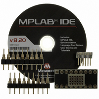
XLT20SS1-1 Microchip Technology, XLT20SS1-1 Datasheet - Page 17

XLT20SS1-1
Manufacturer Part Number
XLT20SS1-1
Description
SOCKET TRANS ICE 20DIP TO 20SSOP
Manufacturer
Microchip Technology
Specifications of XLT20SS1-1
Module/board Type
*
Product
Microcontroller Accessories
Lead Free Status / RoHS Status
Lead free / RoHS Compliant
For Use With/related Products
MPLAB™ICE
For Use With
AC162061 - HEADER INTRFC MPLAB ICD2 20PINAC162060 - HEADER INTRFC MPLAB ICD2 20PINDVA1004 - DEVICE ADAPTER 8/14/20DIPDVA16XP202 - ADAPTER DEVICE PIC16C781/782DVA16XP201 - ADAPTER DEVICE FOR MPLAB-ICEDVA16XP200 - ADAPTER ICE 20DIP/SOIC/SSOPDVA16XP180 - ADAPTER DEVICE FOR MPLAB-ICE
Lead Free Status / RoHS Status
Lead free / RoHS Compliant, Lead free / RoHS Compliant
QFP TRANSITION SOCKET
QFP (MQFP, TQFP, PQFP) transition sockets and
associated hardware are shown below.
FIGURE 4: QFP TRANSITION SOCKET
The QFP transition socket is required for use along with
the QFP device adapter. The device adapter is
equipped with four socket strips that interface with the
transition socket.
There are two parts to the QFP transition socket:
1.
2.
Microchip offers the following QFP transition sockets:
• XLT44PT3: One 44-lead QFP adapter socket and
• XLT64PT5: One 64-lead QFP adapter socket and
• XLT80PT2: One 80-lead QFP adapter socket and
• XLT80PT3: One 80-lead QFP adapter socket and
See the drawings in this section for layout dimensions
and clearances for tall components.
2010 Microchip Technology Inc.
Note:
one 44-lead QFP header (0.8 mm)
one 64-lead QFP header (0.5 mm)
one 80-lead QFP header (0.65 mm)
one 80-lead QFP header (0.5 mm)
Adapter socket that connects to the QFP device
adapter
QFP header that gets soldered down to the
target application
To avoid solder bridging, do not place vias
within 0.025-inch of the QFP footprint.
Also, any vias near the QFP should be
directly on the centerline of the pad.
QFP Transition Socket
QFP Device Adapter
Cable to Processor Module
Target/Application Board
Transition Socket Specification
QFP TRANSITION SOCKET
SOLDERING TIPS
• Use controlled soldering iron tip temperatures
• If possible, use a PACE mini wave soldering iron
• Plan to solder one (1 of 4) side first, then the
• Soldering iron tip movement should be in the
• Use generous amounts of soldering flux to aid in
between 300C and 325C (570F to 615F)
tip or an equivalent tip design.
opposite side, then the remaining two sides.
direction of the leads (backward and forward), not
across the leads; dragging the tip across the
leads may cause lead damage.
the solder flow action.
DS51194S-page 17


