PA16C64-QD-16 Logical Systems Inc., PA16C64-QD-16 Datasheet
PA16C64-QD-16
Manufacturer Part Number
PA16C64-QD-16
Description
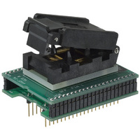
ADAPTER 44-PQFP TO 40-DIP
Manufacturer
Logical Systems Inc.
Datasheet
1.PA16C64-QD-03.pdf
(1 pages)
Specifications of PA16C64-QD-16
Module/board Type
Socket Module - PQFP
For Use With/related Products
PIC16C64A, 65A(B), 67, 662, 74A(B), 774, 77, F874, F877
Lead Free Status / RoHS Status
Contains lead / RoHS non-compliant
Other names
309-1002
PA16C63-QD-16
PA16C63QD16
PA16C64QD16
PA16C63-QD-16
PA16C63QD16
PA16C64QD16
Socket
Supported Device/Footprints
Using this adapter, the Microchip PIC16C64, '65, '67, & ‘74 in
QFP package can be programmed on 40 pin DIP programmers.
The QFP socket accepts packages with the dimensions listed
below:
Which adapter is correct for your package
There are several 44QFP packages. Some devices are available
in more that one 44QFP package. Lookup the lead span for the
package you will be using. Find the matching socket in the table
above. Find the adapter that includes that socket in the Adapter
Construction section.
Logical Systems maintains a device to adapter cross reference
in our office and on our web site. Contact us or visit our web site
to look up a manufacturer and device or package code.
Adapter Dimensions
S Y
44QF-03
44QF-16
Mfgr
Microchip PIC16C64
TQFP
PQFP
S
T E M S
Body
10.0 mm typ
10.0 mm typ
Device
PIC16C65, 65A
PIC16C67, 67A
PIC16C74, 74A
PIC18F4423
PIC18F4523
Device
Logical Systems Corporation
PO Box 6184, Syracuse, NY 13217-6184 USA
Tel (315) 478-0722, FAX (315) 479-6753
www.logicalsys.com, Email: info@logicalsys.com
PA16C64-QD(-03 or -16) Data Sheet
PA16C64-QD-03
Knee
11 mm typ
11.3 mm max
11.6 mm typ
44 pin PQFP or TQFP socket/40 pin DIP 0.6" plug
Packag
e
44 QFP PIC16C64
Device
PIC16C65
PIC16C67
PIC16C74
PIC18F4423
PIC18F4523
Tip (lead span) Pitch
12 mm typ
12.8 mm max
13.2 mm typ
Footprint
Plug
40 pin
DIP
0.8 mm
0.8 mm
Adapter Construction
The adapter is made up of 3 sub-assemblies. They assemble via
connectors making the adapter modular. This way the sub-
assemblies can be replaced easily.
The following chart shows the various socket and board part
numbers that make up these adapters.
When disassembling the adapter take care not to bend the pins.
When reassembling the adapter note the pin 1 indicators to align
the parts correctly.
Test Sockets
Adapter Wiring
The following chart shows the connections from the QFP device
to the adapter’s DIP plug.
Adapter
PA16C64-QD-03
PA16C64-QD-16
LSC #
44QF-03
44QF-16
DEVICE
10
11
12
13
14
15
16
17
18
19
20
21
22
1
2
3
4
5
6
7
8
9
SIGNAL
/MCLR
VDD
RC7
RD4
RD5
RD6
RD7
VSS
RB0
RB1
RB2
RB3
RB4
RB5
RB6
RB7
RA0
RA1
RA2
RA3
Style
Open Top ZIF
Lidded ZIF
N/C
N/C
Socket
44QF-03
44QF-16
PA16C64-QD-16
PLUG
26
27
28
29
30
31
32
33
34
35
36
37
38
39
40
1
2
3
4
5
-
-
Mfgr/Pn
Enplas OTQ-44-0.8-03
Enplas FPQ-44-0.8-16
PLUG
Top Board
44QFP-03
44QFP-16
25
24
23
22
21
20
19
18
17
16
15
14
13
12
11
10
9
8
7
6
-
-
PA16C64-QD Data Sheet
SIGNAL
OSC2
OSC1
Doc: 16C64QD.DOC
VDD
RC6
RC5
RC4
RD3
RD2
RD1
RD0
RC3
RC2
RC1
RC0
VSS
RE2
RE1
RE0
RA5
RA4
N/C
N/C
Rev 01/12/2007
Bottom Board
P64-QD
P64-QD
DEVICE
Page 1 of 1
44
43
42
41
40
39
38
37
36
35
34
33
32
31
30
29
28
27
26
25
24
23
Related parts for PA16C64-QD-16
Image
Part Number
Description
Manufacturer
Datasheet
Request
R

Part Number:
Description:
ADAPTER 44-TQFP TO 40-DIP
Manufacturer:
Logical Systems Inc.
Datasheet:

Part Number:
Description:
ADAPTER 28 PIN .420" PLUGS(6PCS)
Manufacturer:
Logical Systems Inc.
Datasheet:

Part Number:
Description:
ADAPTER 8 PIN .250" PLUGS(6PCS)
Manufacturer:
Logical Systems Inc.
Datasheet:
Part Number:
Description:
ADAPTER 8 PIN .310" PLUGS(6PCS)
Manufacturer:
Logical Systems Inc.
Datasheet:
Part Number:
Description:
ADAPTER 14 PIN .250" PLUGS(6PCS)
Manufacturer:
Logical Systems Inc.
Datasheet:
Part Number:
Description:
ADAPTER 18 PIN .420" PLUGS(6PCS)
Manufacturer:
Logical Systems Inc.
Datasheet:
Part Number:
Description:
ADAPTER 20 PIN .420" PLUGS(6PCS)
Manufacturer:
Logical Systems Inc.
Datasheet:
Part Number:
Description:
PLUG QFP 44PIN (SOLDER DOWN)
Manufacturer:
Logical Systems Inc.
Datasheet:

Part Number:
Description:
ADAPTER 8-DIP BD W/2 SO PLUGS
Manufacturer:
Logical Systems Inc.
Datasheet:

Part Number:
Description:
ADAPTER 28-DIP BOARD
Manufacturer:
Logical Systems Inc.
Datasheet:

Part Number:
Description:
ADAPTER 8-SOIC TO 8-DIP
Manufacturer:
Logical Systems Inc.
Datasheet:

Part Number:
Description:
ADAPTER 8-SOIC TO 8-DIP
Manufacturer:
Logical Systems Inc.
Datasheet:

Part Number:
Description:
ADAPTER 14-SOIC TO 14-DIP
Manufacturer:
Logical Systems Inc.
Datasheet:

Part Number:
Description:
ADAPTER 28-SOIC TO 28-DIP
Manufacturer:
Logical Systems Inc.
Datasheet:

Part Number:
Description:
ADAPTER 20-SOIC TO 20-DIP
Manufacturer:
Logical Systems Inc.
Datasheet: