AC164120 Microchip Technology, AC164120 Datasheet
AC164120
Specifications of AC164120
Available stocks


Related parts for AC164120

AC164120 Summary of contents
Page 1
... PICtail 2004 Microchip Technology Inc. Signal Analysis ™ Daughter Board User’s Guide DS51476A ...
Page 2
... PICLAB, PICtail, PowerCal, PowerInfo, PowerMate, PowerTool, rfLAB, rfPICDEM, Select Mode, Smart Serial, SmartTel and Total Endurance are trademarks of Microchip Technology Incorporated in the U.S.A. and other countries. SQTP is a service mark of Microchip Technology Incorporated in the U.S.A. All other trademarks mentioned herein are property of their respective companies. ...
Page 3
... Lesson 3 – Pulse Width Modulated Generated Sine Wave ......................... 26 Chapter 4. Troubleshooting 4.1 Introduction ................................................................................................... 27 4.2 Common Problems ....................................................................................... 27 Appendix A. Hardware Schematics A.1 Introduction .................................................................................................. 29 Worldwide Sales and Service .................................................................................... 30 2004 Microchip Technology Inc. SIGNAL ANALYSIS PICtail™ DAUGHTER BOARD USER’S GUIDE Table of Contents DS51476A-page iii ...
Page 4
... Signal Analysis PICtail™ Daughter Board User’s Guide NOTES: DS51476A-page iv 2004 Microchip Technology Inc. ...
Page 5
... Signal Analysis PICtail Daughter Board and steps on how to resolve them. • Appendix A: Hardware Schematics – Illustrates the Signal Analysis PICtail Daughter Board hardware schematic diagrams. 2004 Microchip Technology Inc. SIGNAL ANALYSIS PICtail™ DAUGHTER BOARD USER’S GUIDE Preface ...
Page 6
... The revision level of the document. Examples #define START c:\autoexec.bat <label>, <exp> MPASMWIN [main.asm] errorlevel {0|1} " " filename list " [ list_option..., " " list_option ] 0xFFFF, 0x007A char isascii (char, ch); File > Save OK, Cancel <Tab>, <Ctrl-C> MPLAB IDE User’s Guide 2004 Microchip Technology Inc. ...
Page 7
... The web site provides a variety of services. Users may download files for the latest development tools, data sheets, application notes, user’s guides, articles and sample programs. A variety of information specific to the business of Microchip is also available, including listings of Microchip sales offices, distributors and factory representatives. 2004 Microchip Technology Inc. ® ® Acrobat (pdf) format. ...
Page 8
... MPLAB IDE, MPLAB SIM and MPLAB SIM30 simulators, MPLAB IDE Project Manager and general editing and debugging features. Programmers – The latest information on Microchip device programmers. These include the MPLAB PM3 and PRO MATE Plus development programmer. DS51476A-page 4 ® II device programmers and PICSTART 2004 Microchip Technology Inc. ® ® ...
Page 9
... Microchip’s development systems software products. Plus, this line provides information on how customers can receive any currently available upgrade kits. The Hotline Numbers are: 1-800-755-2345 for U.S. and most of Canada. 1-480-792-7302 for the rest of the world. 2004 Microchip Technology Inc. Preface DS51476A-page 5 ...
Page 10
... Signal Analysis PICtail™ Daughter Board User’s Guide NOTES: DS51476A-page 6 2004 Microchip Technology Inc. ...
Page 11
... Real-time Strip Chart • Oscilloscope • Fast Fourier Transformation (FFT) • Histogram • Programming 2004 Microchip Technology Inc. SIGNAL ANALYSIS PICtail™ DAUGHTER BOARD USER’S GUIDE ® device with USB Version 2.0.0 (or later) DS51476A-page 7 ...
Page 12
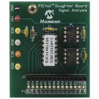
... Signal Analysis board for signal measurement and analysis. All port pins from the PIC16F684 are available on the J1 connector. FIGURE 1-1: DS51476A-page 8 SIGNAL ANALYSIS PICtail™ DAUGHTER BOARD PICtail™ Daughter Board Signal Analysis U2 U3 2004 Microchip Technology Inc. ...
Page 13
... PICmicro device via USB serial communications. This facilitates PC host programs to command, control and communicate with the target PICmicro device that is being evaluated or for program development. 2004 Microchip Technology Inc. Signal Analysis PICtail™ Daughter Board SIGNAL ANALYSIS PICtail™ DAUGHTER BOARD ...
Page 14
... DIAGRAM PICkit™ 1 Flash Starter Kit +5V +5V Busy PIC16C745 RB7 USB 18 RC7 17 RC6 2 RA0 PP V Charge Pump 3 RA1 Circuitry 13 RC2 14 PICA2Dlab Commands Signal Analysis PICtail™ Daughter Board +5V P1 PIC16F684 13 + ICSPDAT RA0 8 8 ICSPCLK 12 RA1 RA3 2004 Microchip Technology Inc. ...
Page 15
... PICmicro device. Check the PIC16C745/765 8-Bit CMOS Microcontroller with the USB data sheet (DS41124), for actual specifications on oscillator tolerances. 2004 Microchip Technology Inc. Signal Analysis PICtail™ Daughter Board PICA2DLAB ACQUISITION MODE DATA FLOW DIAGRAM Queuing ...
Page 16
... Signal Analysis PICtail™ Daughter Board User’s Guide NOTES: DS51476A-page 12 2004 Microchip Technology Inc. ...
Page 17
... Attach the Signal Analysis PICtail Daughter Board to the PICkit 1 Flash Starter Kit as shown in Figure 2-1. FIGURE 2-1: USB Cable PIC16C745 Firmware Version 2.0.0 or later 2004 Microchip Technology Inc. SIGNAL ANALYSIS PICtail™ DAUGHTER BOARD USER’S GUIDE SIGNAL ANALYSIS PICtail™ DAUGHTER BOARD Expansion Header (J3) Signal Analysis PICtail™ ...
Page 18
... Program the PIC16F684 by selecting the Write Device button. 7. Apply the signal under test to pin RC0. The signal voltage level should be between 0V and +5V. DS51476A-page 14 PICkit™ 1 SIGNAL ANALYSIS PC APPLICATION INTERFACE WINDOW Strip Oscilloscope FFT Histogram Chart IMPORT HEX FILE 2004 Microchip Technology Inc. ...
Page 19
... To use the Strip Chart function, click on the Strip Chart button. The Strip Chart window is displayed, as shown in Figure 2-5. To start the conversion process, click Go. Use the Speed (sps) drop-down menu (Figure 2-9) to control the sample speed. FIGURE 2-5: 2004 Microchip Technology Inc. MODE SELECTION STRIP CHART DS51476A-page 15 ...
Page 20
... EEPROMs on the Signal Analysis PICtail Daughter Board. When all conversions are complete, the data is uploaded to the PC for display and analysis. Display options for this mode are the Oscilloscope, Histogram and FFT. DS51476A-page 16 REAL-TIME VALUES AVERAGING VOLTS PER DIVISION 2004 Microchip Technology Inc. ...
Page 21
... Click the Oscilloscope button (Figure 2-2) then Click Go to acquire and display the results according to the sample size and speed selected in the drop down boxes. FIGURE 2-10: 2004 Microchip Technology Inc. SAMPLES AND SPEED SELECTION OSCILLOSCOPE PLOT DISPLAY WINDOW DS51476A-page 17 ...
Page 22
... Hanning bell-shape curve. The side lobes of this window are farther from main lobe as compared to the Hanning Windows. This window is typically used for harmonic analysis of continuous time signals as well as random noise. DS51476A-page 18 FFT DISPLAY FFT Accuracy = (4/(n√N)dB) 2004 Microchip Technology Inc. ...
Page 23
... THD (Total Harmonic Distortion) – The ratio the energy of a fundamental test frequency to the energy of its harmonics appearing in the band of interest. SFDR (Spurious Free Dynamic Range) – The difference in decibels between the input signal and the next largest harmonic. 2004 Microchip Technology Inc. DS51476A-page 19 ...
Page 24
... DS51476A-page 20 HISTOGRAM WINDOW Y-Axis shows the number of times a certain code is returned. Forces display to show a certain range of codes, independent on the actual codes in the data set. The range is set by the values in the Max Code and Min Code boxes. 2004 Microchip Technology Inc. ...
Page 25
... Figure 3-2. For more information about thermistors, see Microchip Application Notes AN685, AN689, AN867 and AN897, available on the PICkit 1 CD-ROM and on the Microchip web site: www.microchip.com. 2004 Microchip Technology Inc. SIGNAL ANALYSIS PICtail™ DAUGHTER BOARD USER’S GUIDE DS51476A-page 21 ...
Page 26
... Signal Analysis PICtail™ Daughter Board User’s Guide FIGURE 3-1: FIGURE 3-2: DS51476A-page 22 THERMISTOR SCHEMATIC +5V Thermistor 10 kΩ @ 25°C RC0 3.3kΩ THERMISTOR STRIP CHART DISPLAY 2004 Microchip Technology Inc. ...
Page 27
... FIGURE 3-3: TABLE 3-1: Component 2004 Microchip Technology Inc Panasonic PNZ334 PIN photodiode. U was chosen to be 64.9 kΩ so that 0.1 µF capacitor for good supply bypass . and C form a low-pass filter for noise performance. Since the 2 2 PHOTODIODE PICtail™ SCHEMATIC DIAGRAM ...
Page 28
... Signal Analysis PICtail™ Daughter Board User’s Guide FIGURE 3-4: FIGURE 3-5: DS51476A-page 24 PHOTODIODE OSCILLOSCOPE SCREEN CAPTURE PHOTODIODE FFT SCREEN CAPTURE 2004 Microchip Technology Inc. ...
Page 29
... FIGURE 3-6: 2004 Microchip Technology Inc. PHOTODIODE HISTOGRAM SCREEN CAPTURE Lesson Projects DS51476A-page 25 ...
Page 30
... Figure 3-8 is the resulting sine wave after the PWM signal in Figure 3-7 has been low-pass filtered. Source code and hex files are available on the CD-ROM. FIGURE 3-7: FIGURE 3-8: DS51476A-page 26 MODULATED PWM SIGNAL (BEFORE FILTERING) SINE WAVE (AFTER PWM FILTERING) 2004 Microchip Technology Inc. ...
Page 31
... U1 of the Signal Analysis PICtail Daughter Board. Check and make sure that the evaluation socket on the PICkit 1 board is empty. FIGURE 4-2: 2004 Microchip Technology Inc. SIGNAL ANALYSIS PICtail™ DAUGHTER BOARD USER’S GUIDE PROGRAMMER NOT FOUND ERROR MESSAGE ...
Page 32
... The PICkit 1 Signal Analysis PC Application was not able to communicate with the firmware in the target PICmicro device on the Signal Analysis PICtail Daughter Board. Ensure that PICA2Dlab.hex has been programmed into the Signal Analysis PICtail Daughter Board. FIGURE 4-3: DS51476A-page 28 END DEVICE ACQUISITION FIRMWARE LOADED ERROR MESSAGE 2004 Microchip Technology Inc. ...
Page 33
... Appendix A. Hardware Schematics A.1 INTRODUCTION This appendix contains the Signal Analysis PICtail Daughter Board Hardware Schematic Diagram. 2004 Microchip Technology Inc. SIGNAL ANALYSIS PICtail™ DAUGHTER BOARD USER’S GUIDE DS51476A-page 29 ...
Page 34
... Signal Analysis PICtail™ Daughter Board User’s Guide FIGURE A-1: DS51476A-page 30 SIGNAL ANALYSIS PICtail™ DAUGHTER BOARD HARDWARE SCHEMATIC DIAGRAM J3 Header Expansion Kit Starter Flash 1 PICkit ™ 2004 Microchip Technology Inc. ...
Page 35
... NOTES: 2004 Microchip Technology Inc. Hardware Schematics DS51476A-page 31 ...
Page 36
... Via Quasimodo, 12 20025 Legnano (MI) Milan, Italy Tel: 39-0331-742611 Fax: 39-0331-466781 Netherlands Waegenburghtplein 4 NL-5152 JR, Drunen, Netherlands Tel: 31-416-690399 Fax: 31-416-690340 United Kingdom 505 Eskdale Road Winnersh Triangle Wokingham Berkshire, England RG41 5TU Tel: 44-118-921-5869 Fax: 44-118-921-5820 05/28/04 2004 Microchip Technology Inc. ...