DV164126 Microchip Technology, DV164126 Datasheet
DV164126
Specifications of DV164126
Available stocks


Related parts for DV164126

DV164126 Summary of contents
Page 1
... Microchip Technology Inc. Low Pin Count USB Development Kit User’s Guide DS41356B ...
Page 2
... PowerMate, PowerTool, REAL ICE, rfLAB, Select Mode, Total Endurance, WiperLock and ZENA are trademarks of Microchip Technology Incorporated in the U.S.A. and other countries. SQTP is a service mark of Microchip Technology Incorporated in the U.S.A. All other trademarks mentioned herein are property of their respective companies. ...
Page 3
... Overview of the HID Mouse Firmware ........................................... 19 2.5.3 Procedure ...................................................................................... 20 Testing the Application ........................................................................... 21 Project Lab 3 (HID Keyboard) ........................................................................... 22 2.6.1 Overview of the HID Keyboard Firmware ...................................... 22 2.6.2 Procedure ...................................................................................... 24 Testing the Application ........................................................................... 27 © 2009 Microchip Technology Inc. LOW PIN COUNT USB DEVELOPMENT KIT Table of Contents USER’S GUIDE DS41356B-page iii ...
Page 4
... Low Pin Count USB Development Kit User’s Guide Project Lab 4 (CDC – Serial Emulator) ............................................................. 28 2.7.1 Overview of the CDC – Serial Emulator Firmware ........................ 29 2.7.2 Procedure ...................................................................................... 31 Installing Application Drivers .................................................................. 37 Establish Communication ....................................................................... 40 Testing the Application ........................................................................... 42 Worldwide Sales and Service .....................................................................................50 DS41356B-page iv © 2009 Microchip Technology Inc. ...
Page 5
... The manual layout is as follows: • Chapter 1. “Overview” • Chapter 2. “Getting Started Project Labs” • Appendix A. “Schematics” © 2009 Microchip Technology Inc. LOW PIN COUNT USB DEVELOPMENT KIT Preface NOTICE TO CUSTOMERS USER’ ...
Page 6
... Optional arguments mcc18 [options] file [options] Choice of mutually exclusive errorlevel {0|1} arguments selection Replaces repeated text var_name [, var_name...] Represents code supplied by void main (void) user { ... } © 2009 Microchip Technology Inc. Examples ® IDE User’s Guide ...
Page 7
... Business of Microchip – Product selector and ordering guides, latest Microchip press releases, listing of seminars and events, listings of Microchip sales offices, distributors and factory representatives © 2009 Microchip Technology Inc. Preface ® IDE installation directory. The Readme files DS41356B-page 3 ...
Page 8
... Technical support is available through the web site at: http://support.microchip.com DOCUMENT REVISION HISTORY Revision A (September 2008) • Initial Release of this Document. Revision B (February 2009) • Corrected document errors DS41356B-page 4 © 2009 Microchip Technology Inc. ...
Page 9
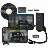
... PIC18F14K50 ICD populated expansion header • (1) CD containing the user guide, course materials and product documentation. • (1) PICkit™ 2 Debugger/Programmer with cable. FIGURE 1-1: © 2009 Microchip Technology Inc. LOW PIN COUNT USB DEVELOPMENT KIT Chapter 1. Overview LOW PIN COUNT USB DEVELOPMENT KIT USER’ ...
Page 10
... J2-J5, J7, J8 are shunted on the bottom side of the board and thus the functions default connected even though no jumper is installed. Cut the jumper to disable the circuitry attached to each pin. DS41356B-page 6 LOW PIN COUNT USB DEVELOPMENT BOARD (Provided by USB regulated 5V to PIC18F14K50 BUS on PIC18F14K50 USB © 2009 Microchip Technology Inc. ...
Page 11
... PIC18F14K50 MCU. Microchip’s USB Device Firmware Framework is introduced as a resource providing a library of firmware code for USB operation that handles “low-level” tasks and a number of reference projects. The user is guided through a number of “hands-on” labs to reinforce covered concepts. © 2009 Microchip Technology Inc. PIC18F14K50 POPULATED MPLAB ICD 2 DEBUG HEADER DS41356B-page 7 ...
Page 12
... Low Pin Count USB Development Kit User’s Guide NOTES: DS41356B-page 8 © 2009 Microchip Technology Inc. ...
Page 13
... In order to complete the Project Labs, the user should have: 1. The most current version of the MPLAB IDE and C18 compiler installed on their PC. The MPLAB IDE can be found at: plg?IdcService=SS_GET_PAGE&nodeId=1406&dDoc- Name=en019469&part=SW007002 © 2009 Microchip Technology Inc. LOW PIN COUNT USB DEVELOPMENT KIT USER’S GUIDE http://www.microchip.com/stellent/idc- ...
Page 14
... Once in the MPLAB IDE, start the Project Wizard by selecting Project>Project Wizard 3. Select the PIC18F14K50 as the device, select the MPLAB C18 C Compiler as the language toolsuite, and create a new project folder in the following directory: C:\Microchip Solutions\Project Lab 1\Project Lab 1 DS41356B-page 10 at:http://www.microchip.com/stellent/idcplg?Idc- http://www.microchip.com/stellent/idcplg?IdcSer- © 2009 Microchip Technology Inc. ...
Page 15
... These files are used by all the applications in the Framework. Therefore, changing these files will affect all applications. If any of these files are inadvertently altered recommended that the Framework be reinstalled. 5. Next, navigate to C:\Microchip Solutions\Microchip\Include and copy over the following files: a) Compiler.h b) GenericTypeDefs.h © 2009 Microchip Technology Inc. DS41356B-page 11 ...
Page 16
... Next the MPLAB IDE will need to be configured for the Framework by directing the C18 compiler to the associated file locations. 11. In the MPLAB IDE, select Project>Build Options…>Project. The Build Options dialog will appear (Figure 2-3). DS41356B-page 12 PROJECT WINDOW FOR LAB 1 © 2009 Microchip Technology Inc. ...
Page 17
... The intention of this lab is to introduce the user to properly configure the firmware so that the PIC18F14K50 will enumerate as a HID mouse once connected to the Host PC. Therefore, the usb_descriptors.c file will need to be altered accordingly © 2009 Microchip Technology Inc. button, navigate to CONFIGURING FOR MICROCHIP USB FIRMWARE ...
Page 18
... USB Spec Release Number in BCD format // Class Code // Subclass code // Protocol code // Max packet size for EP0, see // usbcfg.h // Vendor ID // Product ID // Device release number in BCD format // Manufacturer string index // Product string index // Device serial number string index // Number of possible configurations © 2009 Microchip Technology Inc. ...
Page 19
... Edit>Find in Files in the MPLAB IDE. This will locate all instances of the definition within the project and list them in the Output window. © 2009 Microchip Technology Inc. CONFIGURATION, CLASS SPECIFIC AND INTERFACE // Size of this descriptor in bytes ...
Page 20
... Scroll down to the report descriptor section and copy and paste the code in Example 2-5 between the curly brackets in the section labeled: //ADD REPORT DESCRIPTOR CODE HERE DS41356B-page 16 MANUFACTURER STRING DESCRIPTOR FOR LAB 1 PRODUCT STRING DESCRIPTOR FOR LAB 1 © 2009 Microchip Technology Inc. ...
Page 21
... Enumeration Demo” text placed in the product string earlier in this lab. © 2009 Microchip Technology Inc. REPORT DESCRIPTOR FOR LAB 1 Usage Page (Generic Desktop)*/ ...
Page 22
... The source code developed here is an exact replica of the USB Device - HID – Mouse application found in the Framework. C:\Microchip Solutions\USB Device - HID - Mouse\HID - Mouse – Firmware The user is encouraged to use these files as a reference when needed. DS41356B-page 18 DEVICE MANAGER WINDOW AND HID DRIVERS INSTALLED © 2009 Microchip Technology Inc. ...
Page 23
... Each element of the array is accessed by incrementing the vector variable counter. The buffer array is then loaded into a hid_report_in[] buffer array that is used by the HIDTxPacket macro to transmit the data along the USB to the Host PC. © 2009 Microchip Technology Inc. FLOWCHART FOR THE EMULATE_MOUSE() TRUE = 1 ...
Page 24
... Scroll down to the ProcessIO() function. Note the push button check that toggles the emulate_mode flag. Uncomment the code: //emulate_mode = !emulate_mode; 8. Finally, scroll down to the Emulate_Mouse function and insert the code in Example 2-7 between the curly brackets in the section marked: //ADD EMULATE MOUSE CODE HERE DS41356B-page 20 © 2009 Microchip Technology Inc. ...
Page 25
... Ensure that the Low Pin Count USB Development Board is configured as in Lab 1. 10. Connect the PICkit 2 Programmer and open the PICkit 2 programming software. 11. Navigate to the .hex file located in the C:\LPCUSBDK_Labs\Lab2_files for this lab and download to the PIC18F14K50. © 2009 Microchip Technology Inc. USER DEFINED FUNCTIONAL CODE FOR EMULATE_MOUSE() DS41356B-page 21 ...
Page 26
... ADC module, transmit the numeric value along the USB and display the appropriate character on the screen. This function is implemented as a state machine. The state diagram for this function is shown in Figure 2-5. DS41356B-page 22 CAUTION CAUTION ® shortcut. Great care should be taken to ensure that © 2009 Microchip Technology Inc. ...
Page 27
... If the state condition has been met, the state is changed to the next sequential state. The state variable is declared as a type static as this will allow the current value in the state variable to remain after a return from the keyboard(). © 2009 Microchip Technology Inc. STATE DIAGRAM FOR KEYBOARD() delaycounter < 9000 STATE 0 delaycounter > ...
Page 28
... The report descriptor has changed from the previous lab and will contain 63 components that the Host PC will need to identify this device’s keyboard attributes. 5. Scroll down to the report descriptor and add the code in Example 2-8 in the section labeled: //ADD REPORT DESCRIPTOR HERE DS41356B-page 24 http://www.usb.org/devel- © 2009 Microchip Technology Inc. ...
Page 29
... ADCON0=0x29; // ADCON1 = 0X00; // ADCON2=0x3F; Scroll down to the keyboard() and copy and paste the code in Example 2-9 between the curly braces in the switch at: //ADD STATE MACHINE CODE HERE © 2009 Microchip Technology Inc. REPORT DESCRIPTOR FOR KEYBOARD() // USAGE_PAGE (Generic Desktop) // USAGE (Keyboard) ...
Page 30
... HIDoutput = 29; //Can the SIE transmit? if((HIDTxHandleBusy(lastTransmission) == 0)) { //Load the HID buffer hid_report_in[ hid_report_in[ hid_report_in[2] = HIDoutput; hid_report_in[ hid_report_in[ hid_report_in[ hid_report_in[ hid_report_in[ //Send the 8 byte packet over USB to the host. lastTransmission = HIDTxPacket(HID_EP, (BYTE*)hid_report_in, 0x08); state = 0; } break; //completed © 2009 Microchip Technology Inc. ...
Page 31
... Turn the potentiometer on the Low Pin Count USB Demo Board to change the character on the screen. The user is encouraged to experiment with this application by referring to the Keyboard Usage Page and changing the keyboard packet transmitted in the state machine. © 2009 Microchip Technology Inc. DS41356B-page 27 ...
Page 32
... The only information that is required by the user in the .inf is the Vendor Identification (VID) and Product Identification (PID) numbers specific to their original design. Microchip’s Full-Speed USB Firmware Framework provides all the source code necessary to perform low-level RS-232 functions, thereby abstracting this from the user. DS41356B-page 28 NOTICE © 2009 Microchip Technology Inc. ...
Page 33
... Overview of the CDC – Serial Emulator Firmware The CDC Serial Emulator firmware flow is shown in Figure 2-6. FIGURE 2-6: © 2009 Microchip Technology Inc. FLOWCHART FOR CDC SERIAL EMULATOR CODE ProcessIO( ) RS232 OUT Buffer available and USB OUT Buffer NOT EMPTY ...
Page 34
... It is called once each time through the main program loop. The state machine for the CDCTxService() is shown in Figure 2-7 and the source code can be found in the usb_function_cdc.c source file. The reader is encouraged to reference this firmware and compare it against the state diagram at their leisure. DS41356B-page 30 © 2009 Microchip Technology Inc. ...
Page 35
... Project window. All remaining source/header files will be added from the Project window. 2. Right click on the Source Files folder in the Project window and select Create Subfolder... © 2009 Microchip Technology Inc. CDCTXSERVICE( ) STATE DIAGRAM CDC_TX_BUSY CDC_BULK_BD_IN.Cnt <Max EP Size cdc_tx_len==0 CDC_BULK_BD_IN.Cnt < ...
Page 36
... External to Project, Use Absolute Path” is selected then click Open. FIGURE 2-9: This should add the usb_device.c to the “USB Stack” folder in the Project window. DS41356B-page 32 CREATING A SUB-FOLDER IN THE PROJECT WINDOW ADDING THE USB_DEVICE.C FILE TO THE USB STACK FOLDER © 2009 Microchip Technology Inc. ...
Page 37
... Compiler.h • GenericTypeDefs.h 7. Ensure that the Project Build Options are configured as was done in Lab 1 steps 11 through 15. 8. Compile the project. There should be no errors. The Project window should now resemble Figure 2-10. © 2009 Microchip Technology Inc. DS41356B-page 33 ...
Page 38
... UserInit(). Note that in this function, code has been formatted to allow configuration dependant on the specific device and compiler used. Copy and paste the contents of Example 2-10 into the section of the Initialize- USART() function labeled: //ADD C18 PIC18F14K50 EUSART INITIALIZATION CODE HERE DS41356B-page 34 PROJECT WINDOW FOR LAB 4 © 2009 Microchip Technology Inc. ...
Page 39
... As per the flowchart in Figure 2-6, this code will ensure that the buffer containing the data transmitted from the RS-232 has been sent to the USB firmware. If so, the code then checks for any new RS-232 data that has been stored in the buffer. © 2009 Microchip Technology Inc. INITIALIZEUSART() CODE unsigned char c; ...
Page 40
... ADD THE CODE THAT WILL CHECK IF THE CDC CLASS DEVICE IS READY TO LOAD THE USB BUFFER *********************************************************/ DS41356B-page 36 RS-232 BUFFER CHECK LastRS232Out = getsUSBUSART(RS232_Out_Data,64); if(LastRS232Out > RS232_Out_Data_Rdy = 1; RS232cp = 0;// Reset the current position } TXREG CHECK AND LOAD CODE putcUSART(RS232_Out_Data[RS232cp]); ++RS232cp; if (RS232cp == LastRS232Out) RS232_Out_Data_Rdy = 0; // signal //buffer full © 2009 Microchip Technology Inc. ...
Page 41
... Windows will now prompt the user for driver information. 18. In the “Welcome to the Found New Hardware Wizard” window, select “No, not this time” and then Next (see Figure 2-11). FIGURE 2-11: © 2009 Microchip Technology Inc. CHECK CDC CLASS DEVICE CODE putUSBUSART(&USB_Out_Buffer[0], NextUSBOut); NextUSBOut = 0; ...
Page 42
... Select Browse and navigate to the lab 4 source files in the C:\LPCUSBDK_Labs\Lab4_files\inf\win2k_winxp directory (see Figure 2-13). Highlight the win2k_winxp file and click OK. DS41356B-page 38 SELECTING SOFTWARE LOCATION FOR COMMUNICATIONS PORT © 2009 Microchip Technology Inc. ...
Page 43
... The wizard should indicate that the software for the Communications port was successfully installed. Select Finish. (See Figure 2-14.) FIGURE 2-14: © 2009 Microchip Technology Inc. DIRECTING WINDOWS TO THE .INF FILE FOR THE CDC – SERIAL EMULATOR APPLICATION SUCCESSFUL SOFTWARE INSTALLATION WINDOW ...
Page 44
... Open a Hyper Terminal window by selecting within Windows, Start>Programs>Accessories>Communications>HyperTerminal. The Hyper Terminal Program should now prompt the user for a “Connection Description”. 23. Name this first connection “USB Connection” and click OK. (See Figure 2-16.) DS41356B-page 40 EXAMPLE LIST OF AVAILABLE COM PORTS IN THE DEVICE MANAGER © 2009 Microchip Technology Inc. ...
Page 45
... COM port is on COM7. Note that this may differ on the user’s PC. FIGURE 2-17: 25. In the COM Properties window, configure the connection as shown in Figure 2-18 with a baud rate of 19200 and click Apply then OK. © 2009 Microchip Technology Inc. HYPER TERMINAL CONNECTION DESCRIPTION HYPER TERMINAL CONNECT TO WINDOW DS41356B-page 41 ...
Page 46
... Note that unless configured to echo locally, the originating message COM window will not print the message. The message should be printed in the “USB Connection” COM window as shown in Figure 2-19. DS41356B-page 42 HYPER TERMINAL COM PROPERTIES WINDOW © 2009 Microchip Technology Inc. ...
Page 47
... FIGURE 2-19: This will confirm communication from the Host PC via an RS-232 connection into the PIC18F14K50, which in turn transmits data received back to the Host PC. In other words, an RS-232 to USB conversion. © 2009 Microchip Technology Inc. CONFIRMING RS-232 TO USB COMMUNICATION DS41356B-page 43 ...
Page 48
... Low Pin Count USB Development Kit User’s Guide NOTES: DS41356B-page 44 © 2009 Microchip Technology Inc. ...
Page 49
... CONN, HDR, 1x3 BREAKAWAY, 0.100" PITCH, 0.025 SQ POST, GD (0.100"/0.230") (J14) 1 SOCKET, 20P DIP 0.300W COLLET OPEN FRAME (@XU1) 1 -SPARE- LOCATION (U2 J5, J7, J8) © 2009 Microchip Technology Inc. LOW PIN COUNT USB DEVELOPMENT KIT LOW PIN COUNT USB DEVELOPMENT BOARD BILL OF MATERALS USER’S GUIDE ...
Page 50
... Low Pin Count USB Development Kit User’s Guide A.2 SCHEMATICS FIGURE A-2: PICkit™ 2 USB DEVELOPMENT SCHEMATIC 10K R2 22pF C4 C5 22pF DS41356B-page 0.1uF GND RC2 12 RC1 11 RC0 10 9 D-/ICSPCLK 8 D+/ICSPDAT 7 RC3 6 RC4 5 RC5 4 RA3 3 RA4 2 RA5 1 © 2009 Microchip Technology Inc. ...
Page 51
... OSC1 3 RA4/AN3/OSC2/CLKO OSC2 4 RA3/MCLR/V RA3 PP 5 RC5/CPP1/P1A/T0CKI RC5 6 RC4/P1B/C12OUT/SRQ RC4 7 RC3/AN7/P1C/C12IN3-/PGM RC3 8 RC6 RC6/AN8/SS/T13CKI/T1OSCI 9 RC7/AN9/SDO/T1OSCO RC7 10 RB7/TX/CK RB7 © 2009 Microchip Technology Inc PGD/D+/RA0 D+ 26 PGC/D-/RA1 D- 25 VUSB VUSB +/INT0/C12IN+/AN4/RC0 REF RC0 22 V -/INT1/C12IN1-/AN5/RC1 REF RC1 ...
Page 52
... Low Pin Count USB Development Kit User’s Guide NOTES: DS41356B-page 48 © 2009 Microchip Technology Inc. ...
Page 53
... Low Pin Count USB Development Kit User’s Guide NOTES: © 2009 Microchip Technology Inc. DS41356B-page 49 ...
Page 54
... Fax: 886-3-572-6459 Taiwan - Kaohsiung Tel: 886-7-536-4818 Fax: 886-7-536-4803 Taiwan - Taipei Tel: 886-2-2500-6610 Fax: 886-2-2508-0102 Thailand - Bangkok Tel: 66-2-694-1351 Fax: 66-2-694-1350 © 2009 Microchip Technology Inc. EUROPE Austria - Wels Tel: 43-7242-2244-39 Fax: 43-7242-2244-393 Denmark - Copenhagen Tel: 45-4450-2828 Fax: 45-4485-2829 France - Paris Tel: 33-1-69-53-63-20 ...