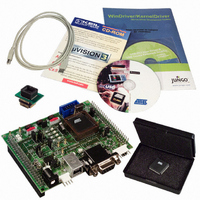
AT89STK-05 Atmel, AT89STK-05 Datasheet

AT89STK-05
Specifications of AT89STK-05
Related parts for AT89STK-05
AT89STK-05 Summary of contents
Page 1
AT89C5131A Starter Kit .............................................................................................. Hardware User Guide ...
Page 2
Table of Contents 1 4245A–USB–11/04 Section 1 Introduction ........................................................................................... 1-1 1.1 Features ....................................................................................................1-1 Section 2 Hardware Description ........................................................................... 2-3 2.1 Block Diagram...........................................................................................2-3 2.2 Power Supply ............................................................................................2-4 2.3 C51 Standard Settings ..............................................................................2-5 2.4 Feature Description...................................................................................2-6 2.5 External Connectors .................................................................................2-8 Section 3 ...
Page 3
Features AT89C5131A Starter Kit Hardware User Guide This document describes the AT89C5131A Starter Kit Evaluation Board dedicated to the AT89C5131A USB microcontroller. This board is designed to allow an easy evalua- tion of the product using demonstration software (refer ...
Page 4
Introduction 1-2 4245A–USB–11/04 Figure 1-1. AT89C5131A Evaluation Board AT89C5131A Starter Kit Hardware User Guide ...
Page 5
Block Diagram AT89C5131A Starter Kit Hardware User Guide Figure 2-1. AT89C5131A Evaluation Board Components USB Power Supply Reset ISP AT89C5131A EA INT0 C51 Generic Board Interface C51 Generic Board Hardware Description Section 2 Hardware Description Device TWI SPI RS232 ...
Page 6
Hardware Description 2.2 Power Supply 2-4 4245A–USB–11/04 The on-board power supply circuitry allows various power supply configurations. The power source can be: – V from USB (5V) BUS – V from USB (5V) through the current limiter BUS – External ...
Page 7
C51 Standard Settings 2.3.1 Reset 2.3.2 Clock 2.3.3 EA 2.3.4 INT0 AT89C5131A Starter Kit Hardware User Guide The external Reset push-button (SW3) is provided to easily generate a warm reset. This button is used for ISP process. The Reset ...
Page 8
Hardware Description 2.4 Feature Description 2.4.1 RS232 Figure 2-5. RS232 On-board Circuitry 2.4.2 USB Peripheral 2-6 4245A–USB–11/04 The AT89C5131A evaluation board includes all the required hardware to manage the RS232 communication. The AT89C5131A evaluation board provides all the required hardware ...
Page 9
TWI Peripheral 2.4.4 SPI Peripheral 2.4.5 LED Controller AT89C5131A Starter Kit Hardware User Guide The CT3 and CT5 contacts have to be soldered in order to use the SDA and SCL alter- nate P4.1 and P4.0 port configuration on ...
Page 10
Hardware Description 2.5 External Connectors 2-8 4245A–USB–11/04 These two external connectors to build a customer extended board easily. Figure 2-7. Top View of J5 and J6 Connectors P1.0 VCC 45 46 P1.1 VSS 44 43 P1.2 SDA ...
Page 11
In-System Programming 3.2 Using a Programmer AT89C5131A Starter Kit Hardware User Guide The user memory of the AT89C5131A part can be programmed using the ISP mode of the device. In order to enter in ISP mode, first select the ...
Page 12
AT89C5131A Starter Kit Hardware User Guide Section 4 Appendix 4-11 Rev. 4245A–USB–11/04 ...
Page 13
Appendix 4.1 Electrical Schematics Electrical Schematics 4-12 4245A–USB–11/ C2- C2 AT89C5131A Starter Kit Hardware User Guide ...
Page 14
AT89C5131A Starter Kit Hardware User Guide Appendix 4-13 4245A–USB–11/04 ...
Page 15
Appendix VDD 16 nc4 46 nc3 34 GND 4-16 4245A–USB–11/04 VSS 41 VSS UVSS 25 UCAP 18 UCAP 2 2 nc15 49 P1.0/T2/KIN0 50 P1_0 P1.1/T2EX/KIN1/SS 51 P1_1 P1.2/ECI/KIN2 52 P1_2 P1.3/CEX0/KIN3 53 P1_3 P1.4/CEX1/KIN4 54 P1_4 ...
Page 16
VDD 16 nc4 46 nc3 34 GND AT89C5131A Starter Kit Hardware User Guide VSS 41 VSS UVSS 25 UCAP 18 UCAP 2 2 nc15 49 P1.0/T2/KIN0 50 P1_0 P1.1/T2EX/KIN1/SS 51 P1_1 P1.2/ECI/KIN2 52 P1_2 P1.3/CEX0/KIN3 53 P1_3 ...
Page 17
Appendix 4-18 4245A–USB–11/ ...
Page 18
Component Placement AT89C5131A Starter Kit Hardware User Guide Figure 4-1. AT89C5131A Evaluation Board Overview 47 45 SPI GND ...
Page 19
Appendix 4.3 Mechanical Outlines 4.4 Bill of Materials 4-20 4245A–USB–11/04 Figure 4-3. AT89C5131A Evaluation Board Mechanical Outlines 2.54 mm C51 Generic Board’s Left connector Table 4-1. Bill of Materials Reference Part C11, C12 2.2 nF C1, C10, ...
Page 20
AT89C5131A Starter Kit Hardware User Guide Table 4-1. Bill of Materials (Continued) Reference Part D2 LED GREEN D1, D7, D9 LEDs RED D3, D4, D5, D6 LEDs PWR GREEN D8 MRA4007 D11 SMBJ9.0A U1 MAX202ECSE U8 DF005S TP1, TP2, TP3, ...
Page 21
AT89C5131A Starter Kit Hardware User Guide Table 4-1. Bill of Materials (Continued) Reference Part SW3, SW4, SW5 PUSH-BUTTON U2 MAX708SCSA U6 TPS2041AD U9 LM1084/TO263 Y1 CRYSTAL Appendix 4-22 4245A–USB–11/04 ...
Page 22
... No licenses to patents or other intellectual property of Atmel are granted by the Company in connection with the sale of Atmel products, expressly or by implication. Atmel’s products are not authorized for use as critical components in life support devices or systems. ...


