STEVAL-IHM015V1 STMicroelectronics, STEVAL-IHM015V1 Datasheet
STEVAL-IHM015V1
Specifications of STEVAL-IHM015V1
Available stocks


Related parts for STEVAL-IHM015V1


STEVAL-IHM015V1 Summary of contents
Page 1
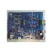
... Introduction The low-voltage motor control demonstration board (also referred to by its order code STEVAL-IHM015V1 complete development platform for low-voltage motor control applications. Based on a cost-effective, flexible and open design, it allows easy demonstration of ST7MC capabilities to drive low-voltage synchronous motors. It includes an ST7MC 8-bit microcontroller with a 16-Kbyte internal Flash memory. The STEVAL- ...
Page 2
Contents Contents 1 System architecture . . . . . . . . . . . . . . . . . . . . . . . . . . . . . . . . . . . ...
Page 3
UM0432 7.4.6 7.4.7 7.4.8 7.4.9 7.4.10 7.4.11 7.4.12 7.4.13 7.4.14 7.4.15 7.4.16 7.5 Driving the BLDC motor (trapezoidal - sensorless 7.5.1 7.5.2 ...
Page 4
Contents 7.7.4 7.7.5 7.7.6 7.7.7 8 Bill of materials . . . . . . . . . . . . . . . . . . . . . . . . . . . . . . . ...
Page 5
UM0432 List of tables Table 1. ST7FMC2S4T6 functions . . . . . . . . . . . . . . . . . . . . . . . . . . . . . . . . ...
Page 6
... List of figures List of figures Figure 1. STEVAL-IHM015V1 . . . . . . . . . . . . . . . . . . . . . . . . . . . . . . . . . . . . . . . . . . . . . . . . . . . . . . . 1 Figure 2. Motor control system architecture Figure 3. STS8DNH3LL . . . . . . . . . . . . . . . . . . . . . . . . . . . . . . . . . . . . . . . . . . . . . . . . . . . . . . . . . . . 12 Figure 4. Board architecture . . . . . . . . . . . . . . . . . . . . . . . . . . . . . . . . . . . . . . . . . . . . . . . . . . . . . . . 14 Figure 5. Power supply architecture . . . . . . . . . . . . . . . . . . . . . . . . . . . . . . . . . . . . . . . . . . . . . . . . . 15 Figure 6. Footprint selection of power devices . . . . . . . . . . . . . . . . . . . . . . . . . . . . . . . . . . . . . . . . . 16 Figure 7. Board layout . . . . . . . . . . . . . . . . . . . . . . . . . . . . . . . . . . . . . . . . . . . . . . . . . . . . . . . . . . . . 17 Figure 8. ICC connector . . . . . . . . . . . . . . . . . . . . . . . . . . . . . . . . . . . . . . . . . . . . . . . . . . . . . . . . . . . 17 Figure 9. SDI connector . . . . . . . . . . . . . . . . . . . . . . . . . . . . . . . . . . . . . . . . . . . . . . . . . . . . . . . . . . . 18 Figure 10. Board schematic: control block . . . . . . . . . . . . . . . . . . . . . . . . . . . . . . . . . . . . . . . . . . . . . . 19 Figure 11. ...
Page 7
... A power block that makes a power conversion from the DC bus transferring it into the motor by means of a 3-phase inverter topology. ● The motor itself. The STEVAL-IHM015V1 board can drive the following kinds of motors. – PMDC (or BLAC/BLDC) permanent magnet motors, 6-step current, both in sensored and sensorless mode. ...
Page 8
... Intended use of the demonstration board The STEVAL-IHM015V1 demonstration board is a component designed for demonstration purposes only, and must not be used for electrical installations or machinery. Technical data and information concerning the power supply conditions are detailed in the documentation and should be strictly observed ...
Page 9
... UM0432 2.5 Operating the demonstration board A system architecture that supplies power to the STEVAL-IHM015V1 demonstration board must be equipped with additional control and protective devices in accordance with the applicable safety requirements (for example, compliance with technical equipment and accident prevention rules). Warning: Do not touch the board immediately after it has been ...
Page 10
ST7FMC2S4T6 microcontroller functions 3 ST7FMC2S4T6 microcontroller functions 3.1 Main features ● TQFP44 package. ● 16 Kbyte dual-voltage Flash program memory with read-out protection capability. ● 768 bytes of RAM (256 stacked bytes). ● Clock, reset and supply management with: – ...
Page 11
UM0432 Table 1. ST7FMC2S4T6 functions Function I/o name MCO0 MCO1 MCO2 MCO3 MCO4 MCO5 MCIA, MCIB, MCIC MCV MTC NMCES OAP OAN OAZ MCC MCPWMV MCZEM MCDEM MISO SPI MOSI SCK RDI LINSCI™ TDO AIN0 AIN1 10-bit ADC AIN13 AIN11 ...
Page 12
STS8DNH3LL characteristics 4 STS8DNH3LL characteristics The STS8DNH3LL is a dual N-channel power MOSFET in SO-8 package (30 V, 0.018 Ω, 8 A), featuring a low gate charge and STripFET™ III. Figure 3. STS8DNH3LL ● DSS = ...
Page 13
... V bias current (typical) V – J5 (low voltage configuration) BUS V – J5 (medium voltage configuration) BUS V – J5 (high voltage configuration) BUS 1. See Section 6.1: Power supply on page 15. Electrical characteristics of the board Table 3 may cause permanent damage to the devices STEVAL-IHM015V1 Min 5 30 (1) 5 (1) 6.5 (1) 9 Unit Max ...
Page 14
... Board architecture 6 Board architecture The STEVAL-IHM015V1 can be schematized as shown in Figure 4. Board architecture Power Supply The control board’s core is the ST7MC microcontroller with a dedicated peripheral included to drive the 3-phase brushless motor. The user interface is made up of four potentiometers (P1, P2, P3, P4) used to set parameters related to the specific drive (see Two push-button switches are also implemented ...
Page 15
UM0432 6.1 Power supply The power supply has been designed to address a wide range of DC bus voltages from Three power supply configurations have been implemented. ● Low voltage: 5–6.5 volts based on the L5970 ...
Page 16
Board architecture dual devices and power MOSFETs in DPAK package. The board is designed to work and 48 V. Figure 6. Footprint selection of power devices Figure 6 shows one of the three legs of the ...
Page 17
UM0432 Figure 7. Board layout 6.3 ICC connector The ICC connector (J1) is used to establish ICC communication for programming/debugging purposes. Its pinout is shown in inDART-STX board (not included in the package). Figure 8. ICC connector Figure 8. This ...
Page 18
Board architecture 6.4 SDI interface (serial data interface) The board is provided with an SDI interface (JP1) to establish SCI communication with external devices. We suggest using an isolation board between the SDI interface and the external devices. The pinout ...
Page 19
UM0432 6.5 Board schematic Figure 10. Board schematic: control block Board architecture 19/53 ...
Page 20
Board architecture Figure 11. Board schematic: power block 20/53 VBoot VBoot VBoot Vcc GND Vcc GND Vcc UM0432 4 11 GND 4 ...
Page 21
... TRIAC, the isolation constraints still apply for switching semiconductor devices such as MOFSETs.) Note: Isolating the application rather than the oscilloscope is highly recommended in any case. 7.2 Hardware requirements To set-up the STEVAL-IHM015V1 demonstration board system, the following items are required. ● The board itself: STEVAL-IHM015V1 ● An insulated DC power supply ● ...
Page 22
Motor control operations 7.3 Software requirements To customize, compile and download the motor control firmware, the following software must be installed. ● "LV ST7MC - GUI" (included in the CD-ROM). ● STVD7 for inDART-STX V.3.11 (also called "ST7 Toolset" downloadable ...
Page 23
UM0432 Figure 12. STVD7 for InDART-STX toolset configuration 7.4 Board setup 7.4.1 Choosing the right firmware The motor control firmware is arranged according to the kind of motor to be driven and to the driving strategy. See Together with the ...
Page 24
Motor control operations 7.4.2 Configuring the firmware using the GUI Before actually using the firmware, it must be configured. The term configure indicates the act of selecting a specific driving strategy, such as open or closed loop, voltage or current ...
Page 25
UM0432 Figure 13. Motor Type Choice window You must select the desired value and press OK. 7.4.4 "3-phase BLAC/DC (trapezoidal)" settings Figure 14. "3-phase BLAC/DC (trapezoidal)" basic parameters window Motor control operations 25/53 ...
Page 26
Motor control operations Table 8. "3-phase BLAC/DC (trapezoidal)" basic parameters Parameter name Poles pairs Number of pole (north/south) pairs in the motor. Manner in which to run the motor, either open loop (without speed regulation) or closed Speed regulation loop ...
Page 27
UM0432 Table 8. "3-phase BLAC/DC (trapezoidal)" basic parameters (continued) Parameter name B-emf rising edge B-EMF rising edge delay coefficient value (from 0 to 255). B-emf falling edge B-EMF falling edge delay coefficient value (from 0 to 255). Closed-loop parameter (only ...
Page 28
Motor control operations Table 9. "3-phase BLAC/DC (trapezoidal)" advanced parameters Parameter name Switches PWM frequency Pulse width modulation (PWM) frequency in kHz. Switches PWM minimum off PWM minimum off time in microseconds (µs) to detect the BEMF. time Complementary PWM ...
Page 29
UM0432 7.4.6 ”3-phase PMAC motor (sinewave)" settings Figure 16. "3-phase PMAC motor (sinewave)" basic parameters window Table 10. "3-phase PMAC motor (sinewave)" basic parameters Parameter name Poles pairs Speed regulation Sensor configuration Synchronous speed Min Max V/F (voltage vs. frequency) ...
Page 30
Motor control operations Table 10. "3-phase PMAC motor (sinewave)" basic parameters (continued) Parameter name Start-up stator frequency Max duration Min rotor frequency to validate closed loop Regulator settings Integral coefficient (Ki) Proportional coefficient (Kp) Sampling time Phase shift Set phase ...
Page 31
UM0432 7.4.7 "3-phase PMAC motor (sinewave)" advanced settings When you click on the Advanced Settings button (see dialog box opens (see (sinewave)" motor type parameters are set. Figure 17. "3-phase PMAC motor (sinewave)" advanced parameters window Table 11. "3-phase PMAC ...
Page 32
Motor control operations Table 11. "3-phase PMAC motor (sinewave)" advanced parameters (continued) Parameters name Voltage level (expressed as a part of the 255 Brake voltage field. Brake min speed Brake stays active until the motor is brought below this rotor ...
Page 33
UM0432 Note: 1 Make sure that the following string: "<firmware name>.elf - 0 error(s), 0 warning(s)" is displayed inside the output pane after the building of the executable. 2 After the building of the executable, ensure that the file "<firmware ...
Page 34
Motor control operations Note error occurs, make sure that the inDART-STX board is connected to the PC. A green LED lights up if the board is connected. 8. Click on File > Load > Code Buffer ...
Page 35
... Figure 22. This configuration is called a running configuration. Remove the ICC flat cable from the board if present. 1. Connect the insulated DC power supply to the J5 connector of STEVAL-IHM015V1, following the serigraphy for polarity. 2. Connect the phases of the motor to the J10 connector of the board and if required, connect the sensor signal to the hall sensor connector J14. ...
Page 36
Motor control operations Figure 22. System setup for running phase 7.4.15 Changing the maximum allowed bus voltage level The board includes an over-voltage protection mechanism that protects the system, preventing the motor from starting if the bus voltage is greater ...
Page 37
UM0432 7.4.16 Changing the maximum allowed current level An over-current protection mechanism is included inside the board to protect the system, disabling all the power switches if the current that flows inside the motor is greater than a given threshold. ...
Page 38
Motor control operations 7.5 Driving the BLDC motor (trapezoidal - sensorless) This section describes how to drive the sensorless brushless permanent magnet motor. You should first check that the board has been set-up for sensorless driving (see 7.5.1 Specific connection ...
Page 39
UM0432 During any state: idle, start, run or brake, a blinking red LED together with the brake of the motor indicates a fault condition. A fault condition is due to one of the following: ● hardware overcurrent: current flowing inside ...
Page 40
... EMF detection during PWM "on" time can be used to solve the problem. More information on this issue can be found in the application notes AN2030, AN1946 and AN1103. The STEVAL-IHM015V1 demonstration board can be configured to detect the BEMF during the PWM "on" time. Sampling of the BEMF can be performed using three different references. ...
Page 41
UM0432 7.5.10 Detecting the BEMF using the internal reference First of all necessary to correctly size the value of the R39, R50 and R63 resistors using the following formula. Equation 4 Set the jumper as described in You ...
Page 42
Motor control operations Also change the following define in the mtc.h file: #define mem_MCRC_GE ((u8)71) 7.6 Driving the BLDC motor (trapezoidal - sensored) This section describes how to drive the brushless permanent magnet motor with three hall 60° sensors. First ...
Page 43
UM0432 After power-on, the control board’s green LED should blink, signaling that the firmware has started to run. After a while a green LED stays on indicating an "idle" state. 7.6.4 Setting the potentiometers Before running the motor, the three ...
Page 44
Motor control operations Table 19. Potentiometer functionality based on open/closed loop driving strategy (continued) P2 Sets the value of the rising delay coefficient from 0 to 255 P3 Sets the value of the falling delay coefficient from 0 to 255 ...
Page 45
UM0432 7.7.2 Specific jumper settings Set-up the board as per the instructions in and Section 7.4.13. Table 21. PMAC SR jumper settings Driving mode PMAC_3PH_SR Set-up the board as per 7.7.3 LED action after power-on Turn on the power supply. ...
Page 46
Motor control operations Note: Turning the P3 potentiometer modifies the "phase shift" parameter. To optimize driving, the correct value of this parameter must be set. Finding the optimum value of the "phase shift" can be useful to monitor the DC ...
Page 47
... V 220 pF/50 V 100 µ Green LED Red LED Green LED STMicroelectronics 1.5KE15A STMicroelectronics STPS1L60A 1N4148 STMicroelectronics STPS2L25U 4-pin strip-line male ICC connector: HE10 male type 2-pin strip-line male 3-pin strip-line male Bill of materials Footprint smd 0805 smd 0805 Through hole ...
Page 48
... A 15 µ kΩ 10 kΩ kΩ - trimmer 100 kΩ - trimmer 100 kΩ - 1/4 W STMicroelectronics STN4NF03L (NC) 330 kΩ - 1/4 W 680 Ω - 1/4 W 470 - 1/4 W 100 kΩ - 1/4 W (NC) 10 kΩ - 1/4 W (NC kΩ - 1/4 W (NC) 100 Ω ...
Page 49
... W 220 Ω - 1/4 W 2.2 kΩ - 1/4 W 0.07 Ω 1.2 kΩ - 1/4 W 2.7 kΩ kΩ - 1/4 W Reset button Start/stop button STMicroelectronics TS271ACD (NC) STMicroelectronics ST7FMC2S4T6 STMicroelectronics M95020-MN3TP/S STMicroelectronics LK112SM50TR STMicroelectronics L4976D STMicroelectronics L6387 STMicroelectronics STS8DNH3LL STMicroelectronics L5970D STMicroelectronics TS274 ...
Page 50
... References 9 References This user manual provides information on how to use the STEVAL-IHM015V1 and its hardware features. For additional information on supporting software and tools, refer to the following documents. 1. ST7MC datasheet: complete information about microcontroller features and peripherals. 2. ST7MC motor control related application notes: complete information about motor control libraries developed for the ST7MC microcontroller ...
Page 51
... UM0432 10 Known limitations The following are the known limitations present on the STEVAL-IHM015V1 board. ● The filter capacitor for the microcontroller’s power supply is physically situated some distance from the micro pins and near to the start/stop button. Pushing this button generates a glitch on the power supply, which in turn triggers the LVD thus causing an unwanted reset ...
Page 52
Revision history 11 Revision history Table 24. Document revision history Date 24-Jul-2007 22-Oct-2008 52/53 Revision 1 Initial release – Changed document title from "Low voltage motor control demo kit" to "Low voltage motor control demonstration board based on ST7MC MCU". ...
Page 53
... UM0432 Information in this document is provided solely in connection with ST products. STMicroelectronics NV and its subsidiaries (“ST”) reserve the right to make changes, corrections, modifications or improvements, to this document, and the products and services described herein at any time, without notice. All ST products are sold pursuant to ST’s terms and conditions of sale. ...