CY3275 Cypress Semiconductor Corp, CY3275 Datasheet
CY3275
Manufacturer Part Number
CY3275
Description
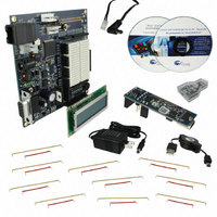
KIT DEV POWERLINE PROGRAM
Manufacturer
Cypress Semiconductor Corp
Type
Other Power Managementr
Specifications of CY3275
Main Purpose
Interface, Transceiver, Powerline Communication
Embedded
No
Utilized Ic / Part
CY8CPLC20
Primary Attributes
2400bps Data Transfer Over Low Voltage Power Lines
Secondary Attributes
User Configurable LEDs
Board Size
101.6 mm x 101.6 mm
Interface Type
RS-232, Ethernet, I2C, ISSP
Maximum Operating Temperature
+ 40 C
Operating Supply Voltage
12 V, 24 V
Product
Power Management Development Tools
Dimensions
101.6 mm x 101.6 mm
Silicon Manufacturer
Cypress
Silicon Core Number
CY8CPLC20
Kit Application Type
Communication & Networking
Application Sub Type
Low Voltage Powerline Communication
Rohs Compliant
Yes
For Use With/related Products
CY8CPLC20
Lead Free Status / RoHS Status
Lead free / RoHS Compliant
Lead Free Status / RoHS Status
Lead free / RoHS Compliant, Lead free / RoHS Compliant
Other names
428-3005


1. Connect the power adapter included in the kit to header J2 on one
Note: Ensure that the LCD module is connected correctly to the LCD1
header. Incorrect connection may cause the board to short circuit.
1. Install and run PSoC Programmer from the Kit CD.
2. Set the device family to PLC20 and the programming mode to
3. Open the PLC20_TX_SP6.hex file from the AppNote 54416
1. On node one, connect eight jumper wires from the DIP switch
1
3
5
of the CY3275 boards (node one). The Blue Power LED powers on.
Reset.
folder on the Kit CD.
header S3 to Port 3 and a jumper wire from the push button switch
header SW to Port 1[6] of the CY8CPLC20.
Using the CY3275 Low Voltage 12-24V AC/DC PLC Development Kit
CY3275 QUICK START GUIDE
1. Attach one end of the custom daisy chain cable to header J3 on
2. Connect the opposite end to header J2 on the other CY3275
1. Attach one end of the MiniProg to the ISSP header J21 on the first
2. Follow the same procedure for the second node using the
1. Push the reset button S1 on both the nodes. A welcome message
2. When you press the push button S4 on the first node, the state of
node one.
board (node two). The Blue Power LED on powers on.
node and the other end to the PC. Connect to the device by
selecting the port. Program the device.
PLC20_RX_SP6.hex file.
appears on the LCD.
the DIP switches S3 is transmitted to the second node and
displayed on the LCD.
6
2
4
[+] Feedback
Related parts for CY3275
Image
Part Number
Description
Manufacturer
Datasheet
Request
R

Part Number:
Description:
Manufacturer:
Cypress Semiconductor Corp
Datasheet:
Part Number:
Description:
Manufacturer:
Cypress Semiconductor Corp
Datasheet:
Part Number:
Description:
Manufacturer:
Cypress Semiconductor Corp
Datasheet:
Part Number:
Description:
Manufacturer:
Cypress Semiconductor Corp
Datasheet:
Part Number:
Description:
Manufacturer:
Cypress Semiconductor Corp
Datasheet:
CY3275 Summary of contents
Page 1
... Attach one end of the custom daisy chain cable to header J3 on node one. 2. Connect the opposite end to header J2 on the other CY3275 board (node two). The Blue Power LED on powers on Attach one end of the MiniProg to the ISSP header J21 on the first node and the other end to the PC ...
Page 2
... CY3275 QUICK START GUIDE Debugger Port (J14) Custom Daisy Chain Header (J3) DC Adapter Connector (J2) RS-232 COM Port (J19) For the latest information about this kit visit www.cypress.com/go/plc © 2009 Cypress Semiconductor Corporation. All rights reserved. All trademarks or registered trademarks referenced herein are the properties of their respective owners ...