DD-DB1-AL202C-FB Matrix Orbital, DD-DB1-AL202C-FB Datasheet
DD-DB1-AL202C-FB
Specifications of DD-DB1-AL202C-FB


Related parts for DD-DB1-AL202C-FB


DD-DB1-AL202C-FB Summary of contents
Page 1
Technical Manual Revision1.1 PCB Revision: 1.0 or greater Firmware Revision: 1.0 or greater ...
Page 2
... Revision 1.0 1.1 0.1 0.2 0.3 0.4 Internal Smaller Magazine Text Reformat 0.5 Internal Re-organization and Connections Addition 0.6 0.7 Minor Changes in preparation of Release 0.8 Command Reformat and Minor Image Fixes (Initial Release) Revision History Description Initial Release Added VFD Option ...
Page 3
Table of Contents Introduction.................................................................................................................................................................................2 Quick Start...................................................................................................................................................................................3 Parts Included.........................................................................................................................................................................................3 Basic Connections...................................................................................................................................................................................4 USB..........................................................................................................................................................................................................5 Serial.......................................................................................................................................................................................................6 I2C...........................................................................................................................................................................................................7 Software......................................................................................................................................................................................8 Numeric Conversion................................................................................................................................................................................8 Hyperterminal.........................................................................................................................................................................................8 uProject...................................................................................................................................................................................................9 Code (C#).................................................................................................................................................................................................9 Hardware...................................................................................................................................................................................10 Advanced Connections..........................................................................................................................................................................10 Screen...................................................................................................................................................................................................11 Serial DB9 Connector.............................................................................................................................................................................11 USB Connectors.....................................................................................................................................................................................12 Power/Communication Header.............................................................................................................................................................12 AC Power Input.....................................................................................................................................................................................13 Protocol Select......................................................................................................................................................................................13 Keypad..................................................................................................................................................................................................14 General Purpose Output.......................................................................................................................................................................14 ...
Page 4
... In addition to the regular 5V, 20mA outputs, indicator LEDs can be enabled beside each GPO to provide status indication. Alternate keys are also added in a tactile style layout, sharing the same pins as the regular keypad. The keypad header also has the same power and ground pins to provide optional grounding or backlight support. ...
Page 5
... Recommended optional equipment available for purchase to use in specific applications, see below Illustration 1: Included* and Optional Parts DevDevil Development Board 3ft mini-B USB Cable Breadboard Development Cable** AC Power Adapter** 4ft Serial Cable** Table 1: Included* and Recommend Parts List 3 DD-20X-XX EXTMUSB3FT BBC ACPC CSS4FT ...
Page 6
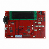
Basic Connections 1 USB Connector 2 Serial DB9 Connector 3 Power/Communication Header 4 AC Power Input Illustration 2: DevDevil Basic Connections 5 Protocol Select Switches 6 Input Select Jumper 7 Voltage Select Jumper Table 2: DevDevil Basic Connections 4 ...
Page 7
USB Cables Required EXTMUSB3FT Illustration 3: USB Connection The USB connection is the quickest, easiest solution for PC development. After driver installation, the DevDevil will be accessible through a virtual serial port, providing the same result as a serial setup ...
Page 8
... Serial protocol provides a classic alternative the the USB method listed above. Two additional cables are required for this connection; the 4 ft serial cable and AC power adapter. These must be purchased in addition to the DevDevil kit. This set up will provide constant regulated power to your development board and provide a familiar communication scheme. To place your board in Serial mode, just adhere to the steps laid out below ...
Page 9
... This time you're on your own. While there are many examples within the Matrix Orbital AppNote section, www.matrixorbital.ca/appnotes, in development, it's a breeze to switch over to another protocol, and fellow developers are always on our forums, http://www.lcdforums.com/forums, for additional support Connection 2 C mode, get started with the guidelines below. ...
Page 10
... Commands can be sent to an attached display by issuing decimal commands using the number pad. While the ALT key is held down, four digit decimal values can be sent as a single ASCII character. For example, to clear the screen try the following sequence. Any commands or text desired can be sent to the communication port using this method to provide total control of any Matrix Orbital display ...
Page 11
... Hello World program, to advanced with the Dallas One-Wire temperature reading application. These programs are meant to showcase the capability of the DevDevil and are not intended to be integrated into a final design. For additional information regarding code, please read the On Code document also found on the support site. display tested using a simple graphical user interface system ...
Page 12
Hardware Advanced Connections 8 Screen* 9 Power Indicator 10 Optional Power Through DB9 11 Serial Communication Indicators 12 Optional Alternate USB 13 USB Communication Indicators 14 Keypad Header *Note: The 4x20 LCD screen shown, the DevDevil is also available with ...
Page 13
Screen The DevDevil provides a twenty character column alphanumeric display that is either two or four rows high. Both of these popular screens are available in an array of colours on a variety of Production modules listed in the appendix ...
Page 14
... Matrix Orbital sales representative. In order to power the DevDevil using USB, ensure that the Voltage Select jumper is removed and the Power Select jumper is set to USB. Please see the USB quick start guide for additional information. Power/Communication Header ...
Page 15
... Mating Cables ACPC In addition to the methods mentioned above, the DevDevil can be powered with adapter. The output voltage of any device must be between 9 and 15 volts DC and the barrel used must be center positive. For this configuration, the Voltage Select jumper must be placed on the 9-15V Input side and the Power Select jumper set to input. This input can be useful when communicating to the device via a computer serial port ...
Page 16
... DevDevil in a 5x5 row, column format. A customizable value is returned to the host each time one of the five row pins is connected to a column pin. Two additional pins are offered on either side of these inputs to provide a single ground and a selectable ground or power pin to provide grounding or backlight capabilities to an external input device ...
Page 17
... Mating Cables Temperature Probe The Dallas One-Wire header affords the ability to add a variety of devices to the DevDevil for purposes ranging from temperature sensing to external memory. Multiple devices can be connected to this bus and accessed using the DevDevil. Only non-parasitic devices, those drawing power from the dedicated pin rather than the data line, have been tested, however, the data line has been pulled high through the nearby resistor to facilitate parasitic operation ...
Page 18
... Reconnect power to your unit, and wait for the start screen before removing the override jumper. 4. Settings will be temporarily overridden to the defaults listed in Table 12: Manual Override Settings. At this point any important settings, such as contrast, backlight, or baud rate, should not only be set but saved so they remain when the override is removed ...
Page 19
... Commands 1. Communications 1.1.Changing the I2C Dec Slave Address Hex ASCII Immediately changes the write address. Address 1 byte, even value 1.2.Changing the Dec 254 57 Baud Rate Hex ASCII Immediately changes the baud rate. Can be temporarily forced to 19200 with manual override. Speed 1 byte, valid settings shown below ...
Page 20
... Clears the contents of the screen. 2.5.Changing the Dec 254 64 Startup Screen Hex ASCII Changes the message displayed on startup. Custom characters can be included by adding their decimal value (0-7). Characters will automatically wrap on the display. Characters 40 bytes for 20x2 screen, 80 bytes for 20x4 Line feed/New line 12 (0CHex) Q ■ ...
Page 21
Auto Line Dec 254 67 Wrap On Hex FE 43 ASCII Text will wrap to the next consecutive line once a row becomes full. Display default is auto line wrap on. 2.7.Set Auto Line Dec 254 68 Wrap Off ...
Page 22
Dec 254 74 Cursor On Hex FE 4A ■ ASCII Displays a line under the current cursor position. Can be used with block cursor. 2.13.Underline Dec 254 75 Cursor Off Hex FE 4B ■ ASCII Removes line under current ...
Page 23
... Creates a custom character. Each character is divided into 8 rows of 5 pixels, each data byte represents one row. Each byte is padded by three zero bits followed by five bits representing each pixel state. A one represents an on condition while a zero is off. Characters are lost when a new memory bank is loaded, unless they are saved. ...
Page 24
Custom Dec Characters Hex Loads a bank of custom characters into memory for use. Must be issued before using a bank of characters. Alternatively, an appropriate initialize command can be used. Bank 1 byte, memory bank ID (0-4) 3.4.Save ...
Page 25
Large Dec Numbers* Hex ASCII Loads the large number custom character bank into memory. Large numbers must be initialized before use. 3.8.Place Large Dec 254 35 Number* Hex FE 23 ASCII Places a single large decimal digit of 4 ...
Page 26
Dec 254 118 Vertical Bar Hex FE 76 ASCII Loads the horizontal bar graph custom character bank into memory. Horizontal bar characters must be initialized before a graph is displayed. 3.12.Place Dec 254 61 Vertical Bar Hex FE 3D ...
Page 27
General Purpose Output 4.1.General Purpose Dec Output Off Hex ASCII Turns the specified GPO off. Will only affect onboard LEDs if LED enable is jumped. Number 1 byte, GPO (1- turned off 4.2.General Purpose Dec Output On ...
Page 28
... Sends a search query to all of the devices on the one wire bus. Any connected device will respond with a identification packet. Response 14 bytes, identification packet as shown below Offset Length Value Description 9002 Preamble 1 138 Another device packet will follow 10 Last device packet 1 49 Packet Type 1 0 Error Code (0 indicates success) 8 Device Address 1 0 CRC8 address check (0 indicates validity ...
Page 29
... Variable, data to be transmitted LSB to MSB Bit Flag Description 7 6 Unused (Future Compatibility) 3 Add CRC8 to transaction 2 0 (Future Compatibility) 1 Read CRC8 from transaction 0 Reset Bus prior to transaction Flags Send Bits Receive Bits Data Flags Send Bits Receive Bits Data Code Error Description ...
Page 30
... MSB will be 0 when the last key press is read. If there are no stored key presses a value of 0 will be returned. Auto transmit key presses must be turned off for this command to be successful. Response 1 byte, value of key pressed (MSB determines additional keys to be read) 6.4.Clear Key Dec ...
Page 31
Auto Dec 254 126 Repeat Mode Hex Sets key press repeat mode to typematic or hold. In typematic mode if a key press is held, the key value is transmitted immediately, then 5 times a second after a 1 ...
Page 32
Display Functions 7.1.Display On Dec 254 66 Hex FE 42 ■ ASCII Turns the display backlight on for a specified length of time inverse display color is used this command will essentially turn on the text. Minutes ...
Page 33
Dec 254 153 Brightness* Hex FE 99 Immediately sets the backlight brightness inverse display color is used this represents the text brightness instead. Default is 255. Brightness 1 byte, brightness level from 0(Dim)-255(Bright) 7.6.Set and Save Dec ...
Page 34
Data Security 8.1.Set Dec 254 147 Remember Hex FE 93 Allows changes to specific settings to be saved to the display memory. Writing to memory can be slow and each change consumes 1 write of approximately 100,000 available. Set ...
Page 35
... Causes display to respond with it's firmware version number. Response 1 byte, convert to hexadecimal to view major and minor revision numbers 9.2.Read Module Dec 254 55 Type Hex ASCII Causes display to respond with it's module number. Response 1 byte, module number, see partial list below 23 DD-DB1-AL202 ■ ■ DD-DB1-AV202 25 DD-DB1-AL204 33 26 DD-DB1-AV204 ...
Page 36
Appendix Character Sets Illustration 17: DevDevil LCD Series Character Table 34 ...
Page 37
Illustration 18: DevDevil VFD Series Character Table 35 ...
Page 38
Environmental Operating Temperature Storage Temperature Operating Relative Humidity Electrical Current Consumption Board 50mA Backlight Consumption 10. 20x2 20x4 Optical Screen Size Viewing Area Active Area Character Size Character Pitch Pixel Size Pixel Pitch Viewing Angle Luminance Backlight Half-Life *Note: A ...
Page 39
Dimensional Drawing Illustration 19: DevDevil Dimensional Drawing 37 ...
Page 40
... Product Type 3 Display Type 4 Display Size 5 Screen Size 6 Color *Note: Available on 20x2 display models only **Note: Available on 20x4 display models only DD -DB1 -AL 202 C - Options DevDevil Development Board, Revision 1.0 -AL: Alphanumeric Liquid Crystal Display -AV: Alphanumeric Vacuum Florescent Display 202: 20 rows by 2 columns 204: 20 rows by 4 columns A: 98 ...
Page 41
Accessories Power ACPC* PC5V PC12V PCUSB *Note: Recommended Optional Accessory AC Power Converter 5V Power Cable 12V Power Cable USB Power Cable Table 17: DevDevil Power Accessories 39 ...
Page 42
Communication CSS1FT CSS4FT** EXTMUSB3FT* INTMUSB3FT SCCPC5V BBC** *Note: Included Accessory **Note: Recommended Optional Accessory 1 ft. Serial Cable 4 ft. Serial Cable Mini-USB Cable Internal Mini-USB Cable Serial Communication/5V Power Cable Breadboard Cable Table 18: DevDevil Communication Accessories 40 ...
Page 43
Peripherals KPP4X4 Temperature Probe 16 Button Keypad Dallas One-Wire Temperature Probe Table 19: DevDevil Peripheral Accessories 41 ...
Page 44
Production Products Display Options Protocol* LK/VK202-25 LK/VK202-25-USB LK/VK204-45 LK/VK204-25-USB USB Not Available RS232 TTL I2C Input Voltage 5V (Regular) 9-15V (-V) 9-35V (-VPT) Connectors DB9 Serial Mini-USB** Power/Data AC Power PC Power*** *Note: Protocol is selected using zero ohm jumper ...
Page 45
... Only the 1x12 keypad header is available on production units, a keypad such as the KPP4X4 unit must be purchased to interface with the display. **Note: Only the 2x7 GPO header is available on production units, indicator LEDs are not available. Additional indicators such as Rx, Tx, and power LEDS are also not offered on production models. ***Note: The Dallas One-Wire header is available on production USB units, but must be specially ordered for non-USB models ...
Page 46
... Matrix Orbital displays are only tested with non-parasitic devices, those that do not draw power from the data line, however, some parasitic devices may work. FFSTN: Double film super-twisted nematic in reference to an LCD. The addition of two layers of film between the STN display and polarizer improves contrast. ...
Page 47
Contact Info Sales Phone: 403.229.2737 Email: sales@matrixorbital.ca Support Phone: 403.204.3750 Email: support@matrixorbital.ca Online Purchasing: www.matrixorbital.com Support: www.matrixorbital.ca 45 ...