EVALPFC2-ICE2PCS01 Infineon Technologies, EVALPFC2-ICE2PCS01 Datasheet
EVALPFC2-ICE2PCS01
Specifications of EVALPFC2-ICE2PCS01


Related parts for EVALPFC2-ICE2PCS01

EVALPFC2-ICE2PCS01 Summary of contents
Page 1
...
Page 2
... Infineon Technologies Office. Infineon Technologies Components may only be used in life-support devices or systems with the express written approval of Infineon Technologies failure of such components can reasonably be expected to cause the failure of that life-support device or system affect the safety or effectiveness of that device or system. Life support devices or systems are intended to be implanted in the human body support and/or maintain and sustain and/or protect human life ...
Page 3
... EVALPFC2-ICE2PCS01 Revision History: 2009-10 Previous Version: Page Subjects (major changes since last revision) 9&10 Capacitor CX1 size changed 300W PFC Evaluation Board with CCM PFC controller ICE2PCS01 License to Infineon Technologies Asia Pacific Pte Ltd Liu Jianwei Luo Junyang Jeoh Meng Kiat ...
Page 4
Content................................................................................................................. 5 2 Evaluation Board ................................................................................................ 5 3 Technical Specifications .................................................................................... 6 4 Circuit Description.............................................................................................. 6 5 Circuit Operation................................................................................................. 6 6 Circuit Diagram ................................................................................................... 8 7 PCB Layout Top Layer ....................................................................................... 9 8 PCB layout Bottom Layer................................................................................. 10 9 ...
Page 5
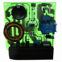
Content The evaluation board described here is a 300W power factor correction (PFC) circuit with 85~265VAC universal input and 393VDC fixed output. Boost converter topology is employed in this board. The continuous conduction mode (CCM) PFC controller ICE2PCS01 is ...
Page 6
Technical specifications: Input voltage Input frequency Output voltage and current Output power Efficiency Switching frequency 4 Circuit Description Line Input The AC line input side comprises the input fuse F1 as over-current protection. The high frequency current ripple is ...
Page 7
Because the peak current limit is not activated, the boost diode is not stressed with large diode duty cycle under high current. Enhanced Dynamic Response Due to inherent low bandwidth of PFC dynamic, in case of load ...
Page 8
Circuit Diagram 120ohm CX1 40uH VAR1 85~265VAC 2*3.9mH S10K275 0.47u/275V N 2.2nF, Y2, 250V Earth C B Vcc C9 47u/25V BR1 RT1 1.24mH 8A, ...
Page 9
PCB layout top layer 9 ...
Page 10
PCB layout Bottom: 10 ...
Page 11
Component List: Designator Part Type BR1 8A, 400V C1 0.1uF/630V C2 220uF/450V C3 0.1uF/50V C4 0.1uF/50V C5 1uF/50V C7 4.7nF/50V C8 0.1uF/50V C9 47uF/25V CX1 0.47uF, X1, 305V CX2 0.47uF, X1, 305V CY1 2.2nF, Y2, 250V CY2 2.2nF, Y2, ...
Page 12
Boost Choke Layout Core: CS468125 toriod Wire Φ1.0mm, AWG19 Inductance: L=1.24mH 11 Test report : 11.1 Load test (table and figure) Vin (VAC) Pin (W) Iin (A) Vout (V) 320 3.8 211 2.51 165 1.96 124 1.47 ...
Page 13
Input Voltage (V) 1 0.9 0.8 0.7 0.6 0.5 0.4 0.3 0.2 0 100 Pout (W) 0.072 ...
Page 14
Harmonic test according to EN61000-3-2 Class D requirement 85VAC, full load (300W output) 85VAC full load (28W output) 265VAC, full load (300W output) Iin Iin Iin 14 ...
Page 15
Waveforms (soft start, load jump, open loop) Soft start, test at 85VAC, Iout=0.2A Load jump test at 85VAC, Iout from 0A to 0.75A Iin Iin Vout Vcc Vcomp Load jump test at ...
Page 16
Open loop test at 265VAC, Iout=0.1A 12 References: Vgate Iin Vout Vsense 16 ...