EVAL-ADM1087EBZ Analog Devices Inc, EVAL-ADM1087EBZ Datasheet

BOARD EVALUATION FOR ADM1087

EVAL-ADM1087EBZ

Manufacturer Part Number
EVAL-ADM1087EBZ
Description
BOARD EVALUATION FOR ADM1087
Manufacturer
Analog Devices Inc
Series
Simple Sequencers®r
Datasheet

Specifications of EVAL-ADM1087EBZ

Main Purpose
Power Management, Power Supply Supervisor/Tracker/Sequencer
Embedded
No
Utilized Ic / Part
ADM1087
Primary Attributes
2 Single Channel Sequencers, Time Based Sequencing
Lead Free Status / RoHS Status
Lead free / RoHS Compliant
Secondary Attributes
-
FEATURES
Sequencing of 3.3 V, 2.5 V, and 1.8 V power supplies
Red, yellow, and green LEDs indicate power supply status,
Dedicated power and enable/disable switches
On-board test points allow examination of ADM1087 and
Sockets allow external through-hole capacitors to be
EVALUATION KIT CONTENTS
ADM1087 evaluation board
9 V battery
2 100 nF ceramic capacitors
4 samples (1 presoldered to on-board adapter)
Rev. 0
Information furnished by Analog Devices is believed to be accurate and reliable.
However, no responsibility is assumed by Analog Devices for its use, nor for any
infringements of patents or other rights of third parties that may result from its use.
Specifications subject to change without notice. No license is granted by implication
or otherwise under any patent or patent rights of Analog Devices. Trademarks and
registered trademarks are the property of their respective owners.
9V
ENABLE/
DISABLE
giving visual demonstration of power-up sequence
regulator I/O signals
connected manually for customizable time delays
9V
ON/OFF
SD
ADP3334
IN
OUT
V
IN
ADM1087
ENIN CEXT
3.3V
3.3V
V
CC
EVALUATION BOARD BLOCK DIAGRAM
ENOUT
RED
SD
ADP3334
IN
Figure 1.
OUT
GENERAL DESCRIPTION
The EVAL-ADM1087EB Evaluation Kit demonstrates how the
ADM1087 Simple Sequencer™ can be used to provide time-
based sequencing in multiple-supply systems. A pair of
ADM1087s are cascaded with three ADP3334 LDO regulators,
which supply voltage levels of 3.3 V, 2.5 V, and 1.8 V. In this
configuration, the 3.3 V supply switches on as soon as power
from a 9 V battery is applied, and the 2.5 V and 1.8 V regulators
are enabled by delayed detection signals from the outputs of the
previous regulators in the circuit.
Red, yellow, and green LEDs provide a visual indication of the
status of each of the three supplies, and two pairs of wire wrap
pins allow for experimentation with different capacitor values
for different enable time delays. A dedicated enable/disable
switch connects directly to the ENIN ADM1087 inputs to
demonstrate how a supply can be switched off by driving this
pin low with an external logic signal.
One Technology Way, P.O. Box 9106, Norwood, MA 02062-9106, U.S.A.
Tel: 781.329.4700
Fax: 781.326.8703
V
ADM1087 Simple Sequencer™
IN
ADM1087
ENIN CEXT
2.5V
3.3V
V
CC
ENOUT
YELLOW
© 2004 Analog Devices, Inc. All rights reserved.
SD
EVAL-ADM1087EB
ADP3334
IN
Evaluation Kit
OUT
www.analog.com
1.8V
GREEN

Related parts for EVAL-ADM1087EBZ

EVAL-ADM1087EBZ Summary of contents

Page 1

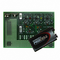
... ADM1087 Simple Sequencer™ GENERAL DESCRIPTION The EVAL-ADM1087EB Evaluation Kit demonstrates how the ADM1087 Simple Sequencer™ can be used to provide time- based sequencing in multiple-supply systems. A pair of ADM1087s are cascaded with three ADP3334 LDO regulators, which supply voltage levels of 3 ...

Page 2

... EVAL-ADM1087EB TABLE OF CONTENTS Power-Up/Power-Down Waveforms.............................................. 3 EVAL-ADM1087EB Schematic ...................................................... 4 Evaluation Board Layout Graphics ................................................ 5 REVISION HISTORY 9/04—Revision 0: Initial Version Ordering Information.......................................................................6 EVAL-ADM1087EB Bill of Materials.........................................6 Ordering Guide .............................................................................7 Rev Page ...

Page 3

... The relationship between the size of the external capacitance and the duration of the enable time delay is given by the following formula × 4.8 × µ CH1 5.00V CH2 5.00V CH3 5.00V CH4 5.00V Figure 2. Sequenced Waveforms Rev. Pr0 | Page EVAL-ADM1087EB M25.0ms CH1 5.7V ...

Page 4

... EVAL-ADM1087EB EVAL-ADM1087EB SCHEMATIC Figure 3. Rev Page ...

Page 5

... EVALUATION BOARD LAYOUT GRAPHICS Figure 4. Evaluation Board Layout Figure 5. Component-Side Silkscreen Figure 6. Solder-Side Silkscreen Rev Page EVAL-ADM1087EB ...

Page 6

... EVAL-ADM1087EB ORDERING INFORMATION EVAL-ADM1087EB BILL OF MATERIALS Table 1. Name Part Type Value C1 CAP 1 µF C2 CAP 1 µF C3 CAP 1 µF C4 CAP 1 µF C5 CAP 1 µF C6 CAP 1 µF C7 Wire Wrap Pins C8 Wire Wrap Pins C9 CAP 1 µF D1 LED D2 LED D3 LED P1 BATT_PP3 Q1 BC850B Q2 BC850B Q3 BC850B 75 kΩ R1 RES 150 kΩ ...

Page 7

... Simple Sequencer SC70-6 Simple Sequencer SC70-6 Simple Sequencer SC70-6 Simple Sequencer SC70-6 Simple Sequencer Rubber Stick-On Feet Package Description Evaluation Board for ADM1087 Simple Sequencer Rev Page EVAL-ADM1087EB Source Part Number Analog Devices ADM1087AKS Analog Devices ADM1085AKS Analog Devices ADM1086AKS Analog Devices ...

Page 8

... EVAL-ADM1087EB NOTES © 2004 Analog Devices, Inc. All rights reserved. Trademarks and registered trademarks are the property of their respective owners. D05074–0–9/04(0) Rev Page ...

Related keywords