CDB5467U Cirrus Logic Inc, CDB5467U Datasheet - Page 16
CDB5467U
Manufacturer Part Number
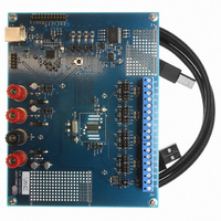
CDB5467U
Description
BOARD EVAL FOR CS5467 ADC
Manufacturer
Cirrus Logic Inc
Type
A/Dr
Specifications of CDB5467U
Main Purpose
Power Management, Energy/Power Meter
Embedded
Yes, MCU, 8-Bit
Utilized Ic / Part
CS5467
Primary Attributes
Watt-Hour Meter
Secondary Attributes
Graphical User Interface, SPI™ & USB Interfaces
Product
Data Conversion Development Tools
Maximum Clock Frequency
4 MHz
Interface Type
USB
Supply Voltage (max)
5 V
Supply Voltage (min)
3.3 V
For Use With/related Products
CS5467
Lead Free Status / RoHS Status
Contains lead / RoHS non-compliant
Lead Free Status / RoHS Status
Lead free / RoHS Compliant, Contains lead / RoHS non-compliant
Other names
598-1555
CDB-5467U
CDB-5467U


4.8 Power and Energy Results
The instantaneous voltage and current samples are
multiplied to obtain the instantaneous power ( P1 , P2 )
(see
N conversions to compute active power ( P1
P2
Apparent power ( S1 , S2 ) is the product of RMS voltage
and current as shown:
Power factor ( PF1 , PF2 ) is active power divided by ap-
parent power as shown below. The sign of the power
factor is determined by the active power.
Wideband reactive power ( Q1
by doing a vector subtraction of active power from ap-
parent power.
16
AVG
Figure 3
).
P1
OFF
(P2
and 4). The product is then averaged over
OFF
)
S
PF
=
V
=
RMS
P
----------------- -
Active
×
S
Q1
Q2
P1
P2
WB
I
S1
S2
RMS
AVG
AVG
AVG
AVG
, Q2
Figure 6. Two-channel Power Summation
WB
Figure 5. Low-rate Calculations
+
+
+
) is calculated
÷2
÷2
÷2
(V2
V1
(I2
I1
ACOFF
ACOFF
ACOFF
ACOFF
AVG
,
Q
E
S
)
)
PULSE
PULSE
PULSE
PulseRate
Quadrature power ( Q1 , Q2 ) are sample rate results ob-
tained by multiplying instantaneous current ( I1 , I2 ) by in-
stantaneous quadrature voltage ( V1Q , V2Q ) which are
created by phase shifting instantaneous voltage ( V1 ,
V2 ) 90 degrees using first-order integrators. (See
ure 3
related to line frequency, so their gain is corrected by
the Epsilon register, which is based on line frequency.
Reactive power ( Q1
grating the instantaneous quadrature power over N
samples.
Active power ( P1
and reactive power ( Q1
are summed up and then divided by 2. The calculation
results are placed in E
isters which can be configured to drive energy pulse
outputs. (See
and 4). The gain of these integrators is inversely
×
×
×
+
+
+
Figure
OVF=
OVF=
OVF=
AVG
( E1, E2, E3 )
Q
Q
E
S
ACCM
ACCM
ACCM
Avg
, P2
WB
6.)
PULSE
AVG
, Q2
=
AVG
, Q2
S
AvG
), apparent power ( S1 , S2 ),
, S
2
–
AVG
PULSE
) is generated by inte-
P
Active
2
) of the two channels
, and Q
CS5467
PULSE
DS714F1
Fig-
reg-
Related parts for CDB5467U
Image
Part Number
Description
Manufacturer
Datasheet
Request
R

Part Number:
Description:
Development Kit
Manufacturer:
Cirrus Logic Inc
Datasheet:
Part Number:
Description:
Development Kit
Manufacturer:
Cirrus Logic Inc
Datasheet:


Part Number:
Description:
High-efficiency PFC + Fluorescent Lamp Driver Reference Design
Manufacturer:
Cirrus Logic Inc
Datasheet:
Part Number:
Description:
Development Kit
Manufacturer:
Cirrus Logic Inc
Datasheet:
Part Number:
Description:
Development Kit
Manufacturer:
Cirrus Logic Inc
Datasheet:

Part Number:
Description:
Development Kit
Manufacturer:
Cirrus Logic Inc
Datasheet:
Part Number:
Description:
Development Kit
Manufacturer:
Cirrus Logic Inc
Datasheet:
Part Number:
Description:
Development Kit
Manufacturer:
Cirrus Logic Inc
Datasheet:
Part Number:
Description:
Development Kit
Manufacturer:
Cirrus Logic Inc
Datasheet:

Part Number:
Description:
EVALUATION BOARD FOR CS8427
Manufacturer:
Cirrus Logic Inc
Datasheet:

Part Number:
Description:
BOARD EVAL FOR CS8416 RCVR
Manufacturer:
Cirrus Logic Inc
Datasheet:

Part Number:
Description:
EVALUATION BOARD FOR CS8420
Manufacturer:
Cirrus Logic Inc
Datasheet:

Part Number:
Description:
KIT DEVELOPMENT EP9315 ARM9
Manufacturer:
Cirrus Logic Inc
Datasheet:

Part Number:
Description:
KIT DEVELOPMENT EP9302 ARM9
Manufacturer:
Cirrus Logic Inc
Datasheet: