CDB5467U Cirrus Logic Inc, CDB5467U Datasheet - Page 25
CDB5467U
Manufacturer Part Number
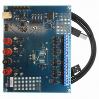
CDB5467U
Description
BOARD EVAL FOR CS5467 ADC
Manufacturer
Cirrus Logic Inc
Type
A/Dr
Specifications of CDB5467U
Main Purpose
Power Management, Energy/Power Meter
Embedded
Yes, MCU, 8-Bit
Utilized Ic / Part
CS5467
Primary Attributes
Watt-Hour Meter
Secondary Attributes
Graphical User Interface, SPI™ & USB Interfaces
Product
Data Conversion Development Tools
Maximum Clock Frequency
4 MHz
Interface Type
USB
Supply Voltage (max)
5 V
Supply Voltage (min)
3.3 V
For Use With/related Products
CS5467
Lead Free Status / RoHS Status
Contains lead / RoHS non-compliant
Lead Free Status / RoHS Status
Lead free / RoHS Compliant, Contains lead / RoHS non-compliant
Other names
598-1555
CDB-5467U
CDB-5467U


7.6 Commands
7.6.1 Conversion
7.6.2 Synchronization (SYNC0 and SYNC1)
7.6.3 Power Control (Stand-by, Sleep, Wake-up/Halt and Software Reset)
DS714F1
B7
B7
B7
1
1
1
All commands are 1 byte (8 bits) long. Many command values are unused and should NOT be written by the
application program. All commands except register reads, register writes, or synchronizing commands will
abort any conversion, calibration, or any initialization sequence currently executing. This includes reset. No
commands other than reads or synchronizing should be executed until the reset sequence completes.
Executes a conversion (measurement) program.
CC
The serial interface is bidirectional. While reading data on the SDO output, the SDI input must be receiving
commands. If no command is needed during a read, SYNC0 or SYNC1 commands can be sent while read
data is received on SDO.
The serial port is normally initialized by de-asserting CS. An alternative method of initialization is to send 3 or
more SYNC1 commands followed by a SYNC0. This is useful in systems where CS is not used and tied low.
The CS5467 has two power-down states, stand-by and sleep. In stand-by, all circuitry except the voltage ref-
erence and clocks are turned off. In sleep mode, all circuitry except the command decoder is turned off. A
Wake-up/Halt command restores full-power operation after stand-by and issues a hardware reset after sleep.
The Software Reset command is a program that emulates a pin reset and is not a power control function.
S[1:0]
B6
B6
B6
1
1
0
B5
B5
B5
S1
1
1
B4
B4
B4
S0
0
1
Continuous/Single Conversion
00 = Software Reset
0 = Perform a Single Conversion (0xE0)
1 = Perform Continuous Conversion (0xE8)
01 = Sleep
10 = Wake-up/Halt
11 = Stand-by
CC
B3
B3
B3
1
0
B2
B2
B2
0
1
0
B1
B1
B1
0
1
0
SYNC
B0
B0
B0
0
0
CS5467
25
Related parts for CDB5467U
Image
Part Number
Description
Manufacturer
Datasheet
Request
R

Part Number:
Description:
Development Kit
Manufacturer:
Cirrus Logic Inc
Datasheet:
Part Number:
Description:
Development Kit
Manufacturer:
Cirrus Logic Inc
Datasheet:


Part Number:
Description:
High-efficiency PFC + Fluorescent Lamp Driver Reference Design
Manufacturer:
Cirrus Logic Inc
Datasheet:
Part Number:
Description:
Development Kit
Manufacturer:
Cirrus Logic Inc
Datasheet:
Part Number:
Description:
Development Kit
Manufacturer:
Cirrus Logic Inc
Datasheet:

Part Number:
Description:
Development Kit
Manufacturer:
Cirrus Logic Inc
Datasheet:
Part Number:
Description:
Development Kit
Manufacturer:
Cirrus Logic Inc
Datasheet:
Part Number:
Description:
Development Kit
Manufacturer:
Cirrus Logic Inc
Datasheet:
Part Number:
Description:
Development Kit
Manufacturer:
Cirrus Logic Inc
Datasheet:

Part Number:
Description:
EVALUATION BOARD FOR CS8427
Manufacturer:
Cirrus Logic Inc
Datasheet:

Part Number:
Description:
BOARD EVAL FOR CS8416 RCVR
Manufacturer:
Cirrus Logic Inc
Datasheet:

Part Number:
Description:
EVALUATION BOARD FOR CS8420
Manufacturer:
Cirrus Logic Inc
Datasheet:

Part Number:
Description:
KIT DEVELOPMENT EP9315 ARM9
Manufacturer:
Cirrus Logic Inc
Datasheet:

Part Number:
Description:
KIT DEVELOPMENT EP9302 ARM9
Manufacturer:
Cirrus Logic Inc
Datasheet: